In today’s volatile energy market, cost control is on top of every asset owner’s mind. And the pressure to reduce costs has created new opportunities for execution strategies from other markets.

This article reviews a recent example of our engineering consulting work with a global chemical processor.

The client agreed to have Vista apply an execution strategy focused on optimized modularization tactics and advanced work packaging (AWP) to their detailed cost estimate for a new facility near Houston.

A Proven Strategy

Vista has combined modularized engineering designs with digital AWP execution for several years now. It has proven to be a very effective strategy to control costs in Alberta’s oilsands sector, where facilities engineered by Vista produce about 1/3 of Canada’s total SAGD production.

Obviously, the construction challenges of northern Alberta’s extreme cold and remote location don’t exist in Texas. And we were excited to see how Vista’s modularization and digital AWP best practices would translate in a different region.


Vista Projects Alberta SAGD production

Demonstrated Savings

The client’s original construction plan involved a “stick building” approach where crews erect most of the facility in the field.

Vista performed an accelerated modularization study and applied principles of our Value Improvement Program (VIP) to find ways to lower the facility’s total installation cost (TIC).

With more than 20 years of applied engineering and modular design know-how, we were able to develop intelligently designed modules that aimed to:

In this example, Vista significantly reduced pipe routing by:

It seems that sound piping design and modularization practices transcend any industry and geography:

We were able to demonstrate a 13% savings.

3D model of a module

Benefits of Modularization

Modularization Optimization

It’s important to highlight that modularization can be overdone.

When a facility design is over-modularized, it leads to inefficiencies and can increase project costs.

The key to finding a project’s modularization sweet spot is to modularize where it makes sense. For Vista, this means focusing on modularizing to reduce costs rather than maximizing modularization in the facility.

Project Cost vs % Modularization graph

Vista’s approach is to develop fit-for-purpose engineering designs and focus on cost-effective solutions. When designing modules, we always look to:

Proper Planning

Modularization optimization requires proper planning.

Before work on the plot plan begins, our expert team will research the location of the facility, associated transportation and logistics considerations, and the accessibility to module fabrication yards.

This research forms part of a detailed transportation study that sets the boundaries for the modularization plan and helps minimize risks later in the project.

In this presentation, Shane Balicki, Vista’s Lead Piping Designer and modularization expert, explains how we optimize modularization in facilities engineering.

Advanced Work Packaging Demo

A key to maximizing the return on your modularization strategy is to empower it with a digital AWP solution.

In the following video, Scott Mussbacher, Systems Integration Lead with Vista Projects, gives a quick demonstration of how we use an integrated digital solution to execute AWP strategies for clients.

Vista is an AVEVA Registered System Integrator and the integrated software solution in the above video showcases our implementation of AVEVA Asset Information Management (AVEVA AIM).

The video also highlights a variety of internally developed project execution software we use on all engineering projects at Vista Projects.


AVEVA registered System Integrator badge

Reduce Your Costs with Modularization + Digital AWP

Combining modularization with digital AWP is a proven cost reduction strategy.

Vista has spent years mastering the approach while engineering facilities in Alberta. Now we’re thrilled to be demonstrating cost savings through optimized modularization to clients in new regions around the world.

If you would like to see how advanced modularization and digital AWP can reduce your facility construction costs, contact Vista Projects today to schedule a consultation.

[fluentform id=”12″]

Carbon Capture

Carbon Capture and Storage (CCS) has become top of mind in oil and gas, energy policy, and sustainability conversations worldwide. But few, apart from the geologists and engineers who work directly in CCS, understand what it is.

This article will be the final of our series on “What Is CSS” and will serve as an introduction to the economics of CSS so that it can be understood by everyone. 

CCS is a broad term that represents several technologies which capture carbon dioxide (CO2) emissions from facilities or directly from the atmosphere. The process is designed to help prevent the accumulation of greenhouse gases in the atmosphere to reduce global warming. Once captured, the CO2 is re-used as a gas in manufacturing processes or is stored via enhanced oil recovery

There is growing interest in the economics and developing markets of CSS in Canada and around the world.

What is Carbon Pricing? 

Carbon pricing is a method used to determine the costs of greenhouse gas (GHG) emissions. Setting a price on carbon helps shift the burden of impact caused by GHG emissions back to those who are responsible for the emissions. This allows the emitters to decide to either transform their activities and lower their pollution output or continue emitting and pay a form of tax on those pollutants. Carbon pricing is, at its core, about recognizing the cost of pollution and accounting for those costs in daily decisions. Putting a price on CO2 is widely recognized as the most efficient means to reduce greenhouse gas emissions while also driving innovation in the energy industry. 

For governments, carbon pricing is seen as a source of revenue. Businesses use carbon pricing for the internal economic evaluation and the impact of mandatory carbon prices on their operations and revenue opportunities. Current carbon price for 2022 in Alberta is roughly $50CAD per tonne (1000kg) of CO2 equivalent greenhouse gas emissions. It remains to be seen if the price of carbon prescribed by the Greenhouse Gas Pollution Pricing Act (GGPPA) will increase to C$170 per tonne of CO2 equivalent emissions by 2030 as described in the federal government’s proposed climate plan entitledA Healthy Environment and a Healthy Economy

Carbon Pricing and the government 

Since 2019, every jurisdiction in Canada has had a price on carbon pollution. Canada’s approach is flexible: any province or territory can design its own pricing system tailored to local needs or can choose the federal pricing system. The federal government sets minimum national stringency standardsthat all systems must meet to ensure they are comparable and contribute their fair share to reducing greenhouse gas emissions. If a province decides not to price pollution or proposes a system that does not meet these standards, the federal system is put in place. This ensures consistency and fairness for all Canadians. 

Under the Greenhouse Gas Pollution Pricing Act (GGPPA), adopted on June 21, 2018, the federal pricing system has two parts: a regulatory charge on fossil fuels like gasoline and natural gas, known as the fuel charge, and a performance-based system for industries, known as the Output-Based Pricing System. The fuel charge applies in Ontario, Manitoba, Yukon, Alberta, Saskatchewan and Nunavut. The Output-Based Pricing System applies in Ontario, Manitoba, New Brunswick , Prince Edward Island, Yukon, Nunavut, and partially in Saskatchewan. All other provinces and territories are implementing their own pricing systems. You can learn more about the Canadian carbon pricing system here.

Pricing carbon pollution is working in Canada. It is encouraging industries to become more efficient and use cleaner technologies, and it is spurring new and innovative approaches for cutting pollution, using energy differently, and saving money. Ultimately, by setting up a market for pollution, it is possible to find a market efficient rate for emissions.


Three Steps for Carbon Capture and Storage Process are:

1) CO2 Capture:  

The separation and capture of CO2 from other gases produced at large industrial process facilities. There are several CO2 capture technologies commonly used in natural gas sweetening and ammonia production used on a commercial scale. Gaps in current knowledge are related to steel and cement production, and differences of component technologies for the capture systems. 

2) Transport: 

Compressed and transported CO2 via pipelines delivered to storage destination. Design will include following: Mechanical design, Protection against corrosion, Trenching and backfilling. 

The costs of pipelines are divided into three items: 


3) Storage:


Enhanced Oil Recovery for CArbon Capture and Sequestration
EOR for Carbon Capture – CO2 and Natural Gas

CO2 is injected into underground rock formations. Injecting CO2 into owned and existing reservoirs carries liability and mineral rights costs for the wells. New saline acquisitions would be run through a pore space application process which will determine initial cost of development if the area is not already owned. 

The cost of transporting and storing carbon varies greatly based on the country in which the storage is taking place and the geological features of the storage area. The greatest variance in storage price comes from the volume of CO2, the transportation distance, and the structural integrity of the storage location itself.

It is also possible for the carbon capture, transport and storage costs to be negative if the returns from enhanced oil recovery, or EOR, are greater than the costs to store the CO2.

As carbon capture and storage costs continue to fall. There is ample opportunity for increased capture and transport efficiencies as the industry of carbon capture and utilization grows. By reaching a carbon capture economy of scale, powered by innovations in the industry, we can expect to see more carbon stored, more effectively, and for reduced costs.


Finding the Optimal CSS Provisioning 

Large scale coal-fired plants are one of the largest contributors to carbon emissions in the industrial space. The cost of carbon capture can generally range anywhere from $120 USD/Tonne to $50 USD/Tonne. This depends on the age of the facility, associated costs of capturing emissions, and other factors specific to each emission site.

Carbon Capture Market Economics


The economic efficiencies which carbon capture relies upon, requires that the overall costs of capture are equal to the benefits they provide. In this case the benefit is largely considered a public good. Following the law of diminishing returns, for every increase in the amount of carbon that is captured, the benefits grow at a smaller rate, and the cost increases. For instance, increasing carbon capture from 0%-10% of emissions would have great public benefit and be relatively inexpensive. Increasing carbon capture from 90%-100% would provide very little added benefit and would be incredibly costly.

By internalising public goods into a defined market between buyers and sellers, largely known as a carbon credit market, a discernable level of efficiency can be estimated. As the market develops and becomes more efficient, the cost to benefit ratio will improve and more carbon capture can occur for the same cost. Thereby increasing public benefit.

Public good is a developing area of economic research, particularly as it pertains to the energy sector. As the economic science of a carbon capture market improves, better levels of efficiency can be achieved.

Planning a carbon capture project?

Vista Projects is an integrated engineering services firm able to assist with your Carbon Capture projects. With offices in Calgary, Alberta, and Houston, Texas, we help clients with customized system integration and engineering consulting across all core disciplines.  


Special thanks to the contributors of this article:

Miodrag Pancic, P.Eng

Carbon Capture and Storage (CCS) has become top of mind in oil and gas, energy policy, and sustainability conversations worldwide. But few, apart from the geologists and engineers who work directly in CCS, understand what it is. 

This article will be the fourth in our series on “What Is CSS” and will serve as an introduction to monitoring, measurement, and verification in Carbon Capture and Storage projects. 

CCS is a broad term that represents several technologies which capture carbon dioxide (CO2) emissions from facilities or directly from the atmosphere. The process is designed to help prevent the accumulation of greenhouse gases in the atmosphere to reduce global warming. Once capturing CO2 is carried out it is re-used as a gas in manufacturing processes or is stored via enhanced oil recovery

There is growing interest in the application of carbon capture and storage technologies to help reduce greenhouse gas emissions in Canada and around the world. This article will provide an introduction into how we monitor, measure, and verify carbon capture processes.

Carbon Capture and Storage in Oil and Gas

Monitoring carbon capture and storage projects

The purpose of monitoring is to identify possible movement of CO2 that may lead to the release of greenhouse gases into the atmosphere. Such events would require immediate remedial action.  Here are the basic steps:

1. Establishing a baseline

Before a project commences, governing bodies require measurement reports to establish a baseline for further operations. This requires a Sequestration Evaluation Permit (SEP) and Carbon Sequestration Lease (CSL).

The  SEP must be obtained before acquiring a CSL. The application for an Evaluation Permit must be submitted to the government regulatory body outlining the Measurement, Monitoring and Verification (MMV) plans. The MMV plan includes steps to measure and monitor the atmosphere, soil, groundwater and subsurface to identify potential CO2 leaks. 

The Sequestration Evaluation Permit (SEP) grants the right to perform detailed testing and characterization of the surface and subsurface environment.

After information about the carbon capture and sequestration site and reservoir bearing has been gathered and evaluated (for example, approx. 15 years of storage capability), a sequestration lease can be obtained. 

2. Carbon capture and storage operations  

During CO2 injection the verification process begins. This verification will help confirm the efficacy of the site.

Verification is the comparison of measured and predicted performance of the CCS operations. In CCS it is defined as the set of activities used for assessing the amount of CO2 that is stored underground, and for assessing how much is leaking back into the atmosphere.

3. Post carbon capture operations and discontinuation 

Monitoring of carbon capture and storage sites continues for decades, to confirm the surrounding area is unaffected and the CO2 is safely contained in the storage site. Below is just some of the monitoring that is undergone at a storage site.

Types of monitoring and measurement: 

Potential escape routes for CO2 injected into saline formations
Figure 1: Potential escape routes for CO2 injected into saline formations.

Escape routes and remediations during carbon capture and storage failure:

A)

B)

C)

D)

E)

F)

G)


Potential Leakage in well cap Carbon Capture and Sequestration
Figure 2: Potential point of leakage in a well undergoing carbon capture and storage. (A) Between cement wall and plug; (B) Through the cement of the cement wall and plug; (C) Between cement wall and pipeline casing; (D) through a breach in the casing; (E) through a breach in the cement wall; and (F) between the cement wall and rock.

Types of Monitoring and Measurement: 

Measurement involves surveillance activities required to ensure the safe and reliable operation of a carbon capture and storage project. Monitoring measurements are an important part of the operations and risk strategy for carbon capture and storage projects.

Subsurface instrumentation monitors the movement of the CO2 in the storage site, the stability of the cap rock, and geological formations above cap rock. 

Integrity evaluation of new and existing wells (Figure 2)

Technologies for monitoring injection rates and pressures/temp

Methods of monitoring CO2 reservoir gas migration

Environmental Monitoring Systems for Carbon Capture and Storage

Environmental Monitoring
Near-surface instrumentation monitors the groundwater to ensure CO2 is not leaking and atmospheric surface instrumentation monitors CO2 levels in the air around the site.

 Groundwater 

Air quality and atmospheric fluxes 

Ecosystems

 The carbon capture and storage in depleted gas reservoirs and enhanced oil recovery (EOR) applications will utilise most of the measurement, monitoring, and verification (MMV) techniques above. However, MMV in EOR application will be slightly different than in depleted gas reservoirs. 

Saline aquifers are a frontier for the current CO2 storage technology and MMV techniques will accordingly change to address potential issues and challenges that will arise. 

Special thanks to the contributors of this article:

Miodrag Pancic P.Eng, Moslem Hosseininejad P.Eng, Darrell Cotterill P.Geol.

Planning a carbon capture project? 

Vista Projects is an integrated engineering services firm able to assist with your Carbon Capture projects. With offices in Calgary, Alberta, and Houston, Texas, we help clients with customized system integration and engineering consulting across all core disciplines.  


Carbon Capture and Storage (CCS) has become top of mind in oil and gas, energy policy, and sustainability conversations worldwide. But few, apart from the geologists and engineers who work directly in CCS, understand what it is.

This article will be the third of our series on “What Is CSS” and will serve as an introduction to CCS geology and reservoir engineering so that it can be understood by everyone. 

CCS is a broad term that represents several technologies which capture carbon dioxide (CO2) emissions from facilities or directly from the atmosphere. The process is designed to help prevent the accumulation of greenhouse gases in the atmosphere to reduce global warming. Once captured, the CO2 is re-used as a gas in manufacturing processes or is stored via enhanced oil recovery

There is growing interest in the application of carbon capture and storage technologies to help reduce greenhouse gas emissions in Canada and around the world.

Geology and Reservoir Engineering With CCUS 

Carbon Capture and Storage (CCS), also known as Carbon Capture Utilisation and Storage (CCUS), is the process of capturing CO2 from a large source, transporting it and storing it underground. Site screening is one of the first steps to evaluate and find geological formations that have the potential for CO2 utilisation and storage. Geological interpretations and modelling can define storage attributes, qualify the storage site and help reduce the risk of CO2 release into the atmosphere.  

The CO2 can be trapped by various formation/reservoir mechanisms when using carbon capture and storage. These mechanisms occur in sequence as the CO2 is injected: 

Structural Trapping 

Residual Trapping  

Solubility Trapping 

Mineral Trapping  

Deep Saline Aquifers 

Deep saline aquifers have the largest estimated capacity for CO2 sequestration. The gas injection phase can often last 10 years or more, depending on the size of the project.  

In the first phase the CO2 displaces the brine already present in the pore space. Although a part of the CO2 dissolves into the salty brine, most of the injected CO2 stays as a gas. The brine holding dissolved CO2 is denser than the original in situ brine and sinks towards the bottom. The density difference between the CO2 in the gaseous state (supercritical condition) and the salt brine causes the gaseous CO2 to migrate upwards to the top of the geologic structure.  

Carbon Capture and Sequestration: Saline Aquifer
Bentham, Michelle, and G. A. Kirby. “CO2 Storage in Saline Aquifers.” Oil & Gas Science and Technology-revue De L Institut Francais Du Petrole 60 (2005): 559-567.


Impermeable sealing strata and faults can stop the further upward movement of the gas, trapping it within the formation. There is another trapping mechanism in this phase called residual trapping which we mentioned above. During CO2 injection both processes are occurring simultaneously.  

In the case of fault seals, the fault ‘throw’, or vertical displacement of the faultline,  and transmissibility of the fault have the most impact on the amount of CO2 that can be injected into a reservoir and stored. Solubility trapping is essential for securing CO2 in deep saline aquifers.  

Most of the stored CO2 stays in the supercritical phase while approximately 10 percent stays dissolved in the aqueous phase for most cases.   

Depleted Gas Reservoirs 

A significant amount of CO2 can be injected into depleted gas reservoirs to collect added natural gas. Mixing of the CO2 and natural gas would be limited because of the high density and viscosity of CO2 compared to methane, which is the largest part of natural gas. The higher the rate of CO2 injection, the higher the natural gas recovery.  

An inverse correlation exists with the sustainability of the injection rate, structural and dissolution trappings, and storage capacity. A reservoir with a high amount of remaining gas may offer a high-pressure build-up elevating the security risk of the reservoir.

It is crucial to select a low injection rate when the level of remaining gas in the reservoir is significant. Choice of the storage medium is essential to achieving an effective storage capacity with sustainable injection rates. 

Enhanced Oil Recovery Reservoirs  

CO2 enhanced oil recovery (CO2-EOR) can displace oil either by an immiscible or miscible displacement process. Miscibility is where two fluids can be mixed in all proportions, forming a single fluid with no interface between them.
Conversely, immiscible fluids do not form a single phase when mixed.

Immiscible displacement occurs when the reservoir pressure is too low, or the oil composition is too heavy, and the injected CO2 gas does not mix with the reservoir oil.  


Carbon Capture: Enhanced Oil Recovery
EOR for Carbon Capture – CO2 and Natural Gas

The minimum miscibility pressure (MMP) finds the minimum pressure required for the reservoir oil to be mixed with carbon dioxide at reservoir temperatures. Miscibility often does not occur in a single point, in many cases multi-contact miscibility is achieved after some gas injection either through condensing gas drive mechanisms or evaporating gas drive processes. Miscible and immiscible displacement processes involve several mechanisms to enhance oil recovery:
 

 Recovery occurs when carbon dioxide is dissolved into the crude oil and the volume of the oil increases. As the volume of oil increases, oil is displaced from the pore space leading to enhanced oil recovery. As the carbon dioxide is dissolved into the crude oil, the oil density and viscosity are also reduced, improving the mobility of the oil.  

CO2 can also provide a gas drive effect where CO2 supplies added reservoir drive energy. Both in immiscible and miscible displacement processes, the injected CO2 changes the residual oil properties to make it more mobile and extractable.  

In some cases, water is initially injected to increase reservoir pressure and to reach MMP before beginning CO2 injection. Some of the best candidate reservoirs for CO2 EOR are mature water-flooded reservoirs with around a 15-25 percent recovery factor. Miscible gas (CO2) flooding in such reservoirs could increase the recovery to 60-90 percent depending on the type of flooding and heterogeneity of the reservoir.  

Geology and Geophysics – A Model for CO2 Sequestration  

The geologic model of a reservoir allows a better understanding of flow conduits, connectivity to any aquifers, faults and fractures, fluid volumes, reservoir connectivity, and different flow units.  


Carbon Capture: Carbon Sequestration Reservoir
Source: Dr. Mauro Cacace, 3D Model of a fractured geological reservoir. Helmholtz Centre Potsdam, GFZ German Research Centre for Geosciences

Steps to be completed before the geological model is developed: 

Dynamic reservoir fluid flow simulation for CO2 injection 

Proper modelling and analysis of carbon capture and storage will require correct fluid modelling, and exact rock-fluid interaction modelling. In fact, once the geological model is built, the two most vital elements needed for modelling and understanding of CO2 sequestration are pressure-volume-temperature (PVT) and special core analysis (SCAL).  

CO2 properties will change significantly with pressure and temperature. Additionally, CO2 miscibility with different fluids can be a complex problem. Many papers are published on experimental data of CO2 interaction with other fluids. If CO2-EOR is the goal, the best approach is to do PVT tests and make a fluid model that matches the experiments.

Otherwise, we can use publicly available experiments with oil properties close to the target reservoir oil and make a fluid model based on that data.  

As an example of the complexity of CO2 fluid behaviour. The density of CO2 at the land surface is around 1.9 kg/m3, but the interplay between pressure and geothermal gradients lead to large density increases until ~600–1000 m depth where it reaches densities between 250 and 800 kg/m3.  

Capillary pressure and interfacial tension (IFT) becomes important as it dictates residual oil saturation, macro-sweep efficiency of the CO2 flooding, and the amount of CO2 storage.   

If CO2 sequestration in aquifers is considered, it is best to follow a compositional approach, as there are only 2 components and run time is manageable while gaining more certainty of the results with a compositional simulator. Compositional simulators have CO2 as one part in the fluid model. In this approach, a normal equation of state (ideally tuned to experimental data) is used to model the interaction of CO2 and other fluids.

Solubility and miscibility could be more accurately modelled using compositional modelling, although it needs good data, and it takes more computing and memory power.  

Subsurface workflow in carbon capture and storage

The focus with subsurface workflow is on site characterization. Carbon capture and storage has some workflow similarities with the oil and gas industry, moreover, CO2 storage has some unique geology and geophysics, and reservoir engineering considerations.  

The workflows will figure out maximum operating pressure, injection rate, injection pattern, capacity & number of wells, and the economic life cycle of the CO2 sequestration.  

The subsurface analysis will include model calibration, economic sensitivity, testing injection scenarios and comparing outputs.  

The site characterization is intended to decide if potential sites can be identified as a prospective area, how it is ranked among potential sites in the vicinity, and if it is considered to meet all necessary criteria for regulatory approval.  

Special Credits and Contributions by: Miodrag Pancic P.Eng, Moslem Hosseininejad P.Eng, Darrell Cotterill P.Geol.

Planning a carbon capture and storage project? 

Vista Projects is an integrated engineering services firm able to assist with your Carbon Capture projects. With offices in Calgary, Alberta, and Houston, Texas, we help clients with customised system integration and engineering consulting across all core disciplines.  

Modularization is a popular trend in industrial facilities engineering, and this is for good reason. When planned from the early stages of engineering and combined with advanced work packaging, the benefits of optimized modularization include reduced costs, shortened schedules, and safer work environments.

Vista has engineered some of the most successful large-scale processing facilities in the Canadian energy sector. A key success factor has been our relentless optimization of modularized designs in facility engineering.

exchanger skid - Modularization 

Below is a video presentation by Shane Balicki, one of Vista’s modularization experts.

Proper Planning

Modularization optimization requires proper planning prior to beginning the engineering design. Before work on the plot plan begins, Vista researches both the location of the facility and the module fabrication yard. This forms part of a detailed transportation study that helps minimize risk later in the project.

Plot Plan Design and Development

With the transportation requirements understood, Vista begins to develop the plot plan and considers the following deliverables, before building the 3D model:

Model development doesn’t begin until the Area Key Plans and the Module Key Plans are complete. Each discipline is given its hierarchy and modelling is based on the area number and module number. This is a highly collaborative, multi-disciplinary process.

[one-half-first]

Optimization Opportunities

Taking advantage of the following opportunities can help reduce cost and increase project efficiencies.

[/one-half-first][one-half]

Modularization Brochure

[fluentform id=”16″][/one-half][clearfix][vertical-spacer]

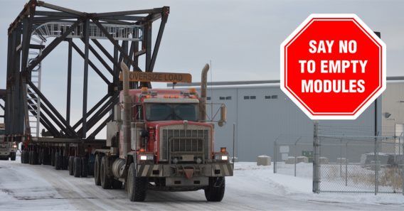
Say No to Empty Modules

[three-fifths-first]

With proper planning, there is no need to ship air to the site.

When designing modules, Vista always looks to:

[/three-fifths-first]
[two-fifths]Modularization Optimization - Say No to Empty Modules[/two-fifths][clearfix]
[columns-container]

Fit-for-Purpose Design

An over-modularized design can increase project costs. The key to finding a project’s modularization sweet spot is to modularize where it makes sense and focus on optimization over maximization.

Vista’s approach is to develop fit-for-purpose engineering designs and focus on cost-effective solutions.

Project Cost vs % Modularization

Project Cost vs Modularization %
[/columns-container][vertical-spacer]

Module Reporting

As with all elements of project execution, Vista takes a data-centric approach to modularization. This streamlines module reporting and gives our clients access to a live technical directory, in which they can view key metrics in a user-friendly dashboard and export module lists, isometric skid drawings, MTOs module weights, and more.

The technical directory uses Vista’s intelligent engineering data to cross-reference all elements and gives all stakeholders near-live access to everything they need to know about the project.

Module Reporting dashboard

[columns-container]

Contact Vista About Modularization

[fluentform id=”12″][/columns-container]

Economical in-situ thermal technology has been long sought after in the petroleum extraction industry.

[two-fifths-first]

To supplement conventional oil production, many producers have shifted their focus to unconventional oil. One example of this resource is the bitumen present in Canada’s oil sands, but Canada is not the only bitumen-rich country in the world.

Over 30 countries are known to possess recoverable heavy oil, including Venezuela, Saudi Arabia, and the United States.

In Canada, 80% of the heavy oil and bitumen present cannot be extracted through regular surface mining methods. Due to its highly viscous nature, heavy oil and bitumen cannot flow naturally to the wells that are drilled without being heated.

In pursuit of these resources, extensive research has been done, which has led to the discovery of many innovative thermal technologies over the years.

[/two-fifths-first]

[three-fifths class=”grey-background”]

Table of Contents

In-situ Combustion
Variations of In-situ Combustion Technology
» Toe-to-Heel Air Injection (THAI)
» Catalytic Upgrading Process In-situ (CAPRI)
» Steamflooding
» Cyclic Steam Stimulation (CSS)
» Steam-Assisted Gravity Drainage (SAGD)
Variations of SAGD Technology
» Vapour-Assisted Petroleum Extraction (VAPEX)
» Solvent-Assisted Steam-Assisted Gravity Drainage (SA-SAGD)
» Steam and Gas Push (SAGP)
» Electromagnetic (EM) Heating
3 Methods for Electromagnetic Heating
» Downhole Electric Heaters
» Radio Frequency (RF) Heating
» Electric Resistive Heating
In-situ Thermal Technology Recap
[/three-fifths]

[clearfix]

Reserves that were previously considered inaccessible are now bringing thousands of barrels of heavy oil and bitumen to the surface every day. From steam flooding to in-situ combustion, to electromagnetism, a brief look into the history of in-situ thermal technology shows just how far the industry has come.

In-situ Combustion

In-situ combustion is the oldest of all the thermal enhanced oil recovery (EOR) technologies. Adopted in the 1920s, many operators have deemed it an unsuitable method for oil recovery because of the number of failed operations when it was first being tested. Operators struggled to control which way the fire burned. However, advancements in this in-situ thermal technology indicate that higher recovery rates can be reached in certain formations, with proper engineering practices in place.

In this process, an injection well and a production well are drilled. In-situ combustion requires the injection of a gas to start a fire within the reservoir. The fire burns through roughly 10% of the oil in place as it makes its way towards the production well and to keep the fire burning, air is injected into the reservoir. The burning oil also leaves behind a coke residue, which further fuels the fire. The oil is pushed towards the production well by the combusted gases and the water within the formation.

The two methods for in-situ combustion are forward and reverse. During forward combustion, the fire advances in the direction of the air flow. In reverse combustion, the fire travels in the direction that is opposite to the air flow. Forward combustion is the more popular method and it can be further defined by its “wet” or “dry” process.

When dry forward combustion takes place, only air is injected into the reservoir to keep the fire burning. In wet forward combustion, both water and air are injected into the reservoir. The water vaporizes into steam when it reaches the reservoir, due to its high temperature. The steam travels ahead of the fire and lowers the viscosity of the oil. This increases the speed of the process.

Variations of In-situ Combustion Technology

Let’s look at the various ways in-situ thermal technology uses combustion.

Toe-to-Heel Air Injection (THAI)

THAI technology was developed by Malcolm Greaves in late 1990s. It was first field tested in the Athabasca Whitesands in Canada from 2006-2011 and its recovery rates are between 70% and 80%.

For this method, a horizontal production well is drilled, and a vertical well is drilled at its toe. Steam is injected into the vertical well to heat the surrounding area. Afterward, the air is injected and a fire is ignited. Injection of air continues to fuel the fire and it moves toward the heel of the horizontal well. As it burns, it heats the oil in place and allows it to drain into the horizontal production well.

Catalytic Upgrading Process In-situ (CAPRI)

The CAPRI method was invented in 1998. Recovery rates are between 70% and 80%.

Considered the catalytic extension of THAI, CAPRI uses the same well setup and air injection methods. However, the difference is that hydro-treating catalysts are packed around the horizontal production well. This ensures that oil passing through the well is upgraded in-situ. The benefit to this technique is that less upgrading of the oil is required above the surface, which makes the process more cost-efficient.

Steamflooding

Steamflooding started in 1952, when Shell Oil Co. did a steam drive pilot in the Yorba Linda field of California. By the late 1970’s, it had become a commonly used technology in California. Recovery rates are usually between 50% and 60%.

In a traditional steamflood, several vertical wells are drilled. Some of the wells are injectors and some are producers. Steam, generally with a quality of 80% (80% vapour, 20% liquid) is injected into the formation and it heats up the surrounding oil. As the steam travels further from the injection wells, it condenses into hot water. The hot water helps the oil to expand and it provides a driving force on it. This makes it easier for the oil to travel to the producing well.

Similar to steamflooding is the hot water drive method. Instead of steam being injected into the reservoir, hot water is injected instead. It lowers the viscosity of the oil and pushes it towards the production well. This process is more cost-efficient, but it is better suited for producing lighter oil.

Cyclic Steam Stimulation (CSS)

Cyclic steam stimulation, also called Huff n’ Puff, was discovered by accident in Eastern Venezuela in 1959. It was developed throughout the 1960’s and 1970’s and it became a commercially viable thermal in-situ technology in 1979. Expected recovery rates are from 10% to 40%.

CSS requires the drilling of one well that both injects steam and produces heavy oil and bitumen. The process has 3 stages: injection, soaking and production. The injection stage involves the injection of steam into the reservoir for several weeks. The steam is then allowed to “soak” into the reservoir. Soaking time can vary from a few days to several weeks as the steam heats the oil to make it less viscous.

Finally, the oil can flow to the well, where it is pumped to surface. This cycle is repeated until it is no longer profitable to do so.

Steam-Assisted Gravity Drainage (SAGD)

In 1978, Roger Butler, a chemical engineer working with Imperial Oil, had the idea for SAGD technology. In 1987, it was tested underground for the first time by the Alberta Oil Sands Technology and Research Authority (AOSTRA). SAGD technology became commercialized in 2001 by Cenovus Energy at Foster Creek. With oil recovery rates of up to 40-60%, it has become an aggressive competitor in the field of in-situ thermal technology.

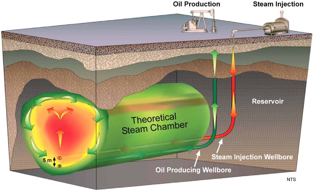
SAGD requires the drilling of a horizontal injection well, and a horizontal production well approximately 5m below it. Steam is continuously injected into the reservoir through the injection well and it heats the surrounding oil and bitumen. As the viscosity of the oil decreases, its mobility increases and it flows downward to the production well. It is then pumped to the surface.

Variations of SAGD Technology

[one-half-first]

There are many SAGD variations within in-situ thermal technology.

Vapour-Assisted Petroleum Extraction (VAPEX)

This variation of SAGD was introduced by Roger Butler in 1991. The recovery rates for this process can be up to 80%.

VAPEX technology is similar to SAGD, except that a solvent in vapour form is injected into the reservoir. The solvent can be methane, ethane and/or propane. The solvent dissolves into the heavy oil or bitumen and the mixture drains towards the production well. Once it is brought to surface, the solvent is stripped from the oil and recycled back into the injection well.

[/one-half-first]

[one-half class=”grey-background”]

Did you know?

Heavy Oil Experts, engineering firm Calgary, oil & gas engineering, engineering consultingFacilities engineered by Vista produce about 1/3 of Alberta’s total SAGD production.

[/one-half]

[clearfix]

Solvent-Assisted Steam-Assisted Gravity Drainage (SA-SAGD)

An SA-SAGD pilot project for this method was first conducted by Imperial Oil in Cold Lake, Alberta in 2006. In this process, steam is injected into the reservoir, but it is mixed with 5% to 20% by volume of hydrocarbon solvent. Like VAPEX technology, the solvent dissolves into the heavy oil or bitumen, and helps it move to the production well. The use of solvents lowers the amount of steam required.

Steam and Gas Push (SAGP)

SAGP was created in 1997 by Roger Butler and his research group.

The SAGP method involves the injection of a non-condensable gas into the reservoir, in combination with steam. The gas lingers at the top of the steam chamber and it helps to preserve the heat that the steam generates. This reduces the amount of steam required and it increases the efficiency of the system.

Electromagnetic (EM) Heating

The earliest field tests for electromagnetic heating were done in the Ishimbayskoye Oil Field in Russia in 1969. They were ultimately unsuccessful due to the high cost and technological difficulties, so many companies lost interest. However, a desire to lower the environmental impact made from producing oil, and advancements in technology have led to a renewed interest in electromagnetic heating. Although it is not yet considered a commercially viable method for in-situ thermal operations, it shows promise for the future.

EM heating can be used in the reservoirs that would otherwise be unattractive for steam injection methods.  This includes reservoirs that are thin, shallow, heterogeneous, fractured, have a high water saturation, and/or do not have a caprock. It can also be used to pre-heat the reservoir before steam is injected. This increases the efficiency of the process and it lowers the amount of steam required.

3 Methods for Electromagnetic Heating

In-situ thermal technology includes three methods for electromagnetic heating.

Downhole Electric Heaters

The idea for using electric heaters was first considered in the 1940’s.

The simplest way of applying heat electrically is to lower electric heaters downhole. The heater is placed in direct contact with the formation and it uses thermal conduction to release heat. Unfortunately, when using electric heaters, it can take a long time to heat the formation and the heat is not spread uniformly. Therefore many companies do not consider it to be a viable option in in-situ thermal operations.

Radio Frequency (RF) Heating

The concept of RF heating in-situ was first introduced in the 1970’s.

RF heating involves putting a large antenna into the ground, where it emits an electromagnetic field. The field is then converted into heat, which is used to lower the viscosity of the surrounding oil. Wells used to collect the oil can be either vertical or horizontal. An advantage to this method is that as it vaporizes the water surrounding the antenna into steam, the electromagnetic field reaches further into the reservoir and heats a different area.

Electric Resistive Heating

The first application of electric resistive heating in-situ was in 1981.

In this process, two electrodes are placed inside the wells that are drilled. They are connected to an AC source and a current is run through them. The water in the formation acts as a conductor and the electrical energy turns into heat. This process works best if many wells are drilled, because the heat generated is highest around the wells, and it decreases as the distance from them increases.

In-situ Thermal Technology Recap

A look at the history of in-situ thermal technology shows that oil companies are always exploring new ways to access the resources that were otherwise considered inaccessible. These technologies have helped to improve the efficiency of projects while lowering the cost and increasing production. Even with the dramatic increase in recovery rates from the first technologies implemented to where the industry is today, research is ongoing, and improvements will continue to be made. The oil industry shows no signs of slowing its quest for innovation anytime soon.

New oil sands technology using solvents injected with steam into bitumen reservoirs can improve the economics of Alberta’s oil production, reports a story in the Financial Post. Major oil sands companies are exploring ways to use chemical solvents to produce more oil while using less water and creating fewer emissions. The new process, known as solvent-assisted steam-assisted gravity drainage (SA-SAGD), will also help producers to lessen the environmental impacts of their operations.

Oil Sands Technology Evolving

SA-SAGD Oil Sands Technology
The SA-SAGD process adds solvents to the injected steam used in typical SAGD oil sands technology (illustrated).

The SA-SAGD process builds on the predominant oil sands production process, SAGD. The SAGD process injects high-pressure steam into bitumen deposits. The steam melts the bitumen so it can be pumped to the surface using conventional wells.

Adding solvents to the steam reduces the amount of water needed. This in turn reduces the emissions involved with generating steam. Imperial Oil’s vice president of upstream engineering, Rick Gallant, expects SA-SAGD to reduce both water use and greenhouse gas emissions per barrel by 25%.

Imperial is currently holding public consultations regarding their Cold Lake Expansion Project which will use SA-SAGD technologies.

Vista Projects – SA-SAGD Experts

Vista Projects has an extensive portfolio of both conventional SAGD and SA-SAGD projects with an array of leading oil sands producers.

Engineering manager Shane Torwalt comments on the Vista approach: “SA-SAGD designs include recovery and recycling of the solvent so that it’s not lost from the system. Just as we design our plants to recycle as much water as possible (to be injected down-hole as steam), our solvent-assisted designs also recycle injected solvent once it returns to the surface with the produced emulsion.”

Torwalt continues, “Typically, we establish a solvent and steam re-use factor (SSRF) for our design and then shape our engineering decisions around meeting or exceeding that number. Our goal is to achieve the highest possible SSRF while remaining mindful of governmental regulations and our client’s project economics.”

Innovation Could Improve Economics

In addition to its environmental benefits, SA-SAGD could also improve the economic viability of oil sands projects. The process has been shown in the laboratory to boost bitumen production in comparison with standard SAGD operations. This could mean more barrels of oil produced for similar investments in infrastructure.

Reduced Need for Pipeline Capacity

Another potential benefit of SA-SAGD is that the oil it produces is less viscous than bitumen produced without solvents. This is significant because, at present, most oil sands producers need to blend their bitumen with a diluent before pipelines can carry it. This means the pipelines end up carrying less bitumen than they could be. Limited pipeline capacity is currently a major choke-point for getting oil sands products to market.

Processes similar to SA-SAGD can produce a pipeline-ready oil. This would remove the need for diluent blending and significantly increase pipeline capacity.

Read More

To read the full article, visit the Financial Post’s website.

World Heavy Oil Congress

We’re pleased to announce Project Manager Patrick Reilly will give a technical presentation at the upcoming World Heavy Oil Congress on how Vista successfully completed the oil sands industry’s largest and most comprehensive implementation of a digital engineering environment.

The 30-minute presentation will include an overview of the results achieved by Vista on the front-end engineering design (FEED) for an oil sands project, which used four amazing cost reduction initiatives in addition to an integrated digital engineering environment.

The audience will also see a walk-through demonstration of a simulated digital engineering environment, powered by AVEVA’s Integrated Engineering and Design (IE&D) solution.

Vista and the client team worked collaboratively to reduce project costs through a variety of initiatives, including these four:

  1. Process simplification
  2. Plot plan compression
  3. Fit-for-purpose specifications, and
  4. Increased modularization

Digital Engineering Environment

The team also identified an opportunity to optimize project execution through integrated engineering in a digital environment using AVEVA IE&D. With the FEED phase ending this quarter, Vista expects to complete the project 16% under budget.

Says Patrick about the impact of a digital engineering environment:

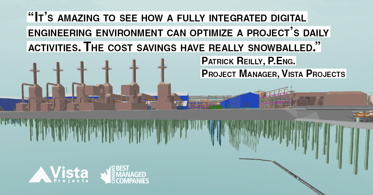
“The efficiencies are greater than we anticipated. It’s amazing to see how a fully integrated digital engineering environment can optimize a project’s daily activities. The cost savings have really snowballed. We’re excited to see the impacts on later project phases.”

Titled Cost Reduction through Integrated Engineering in a Digital Environment”, the presentation is scheduled for 3 p.m. on September 8 as part of the conference’s Surface Facility stream. 2016 marks the eighth World Heavy Oil Congress and the first time the event is held in Calgary.

The event brings together the brightest minds from around the world to share the latest business and technological advancements and insights to provide powerful tools to the industry.

Engineering Project Management:

If you have an engineering project that could benefit from Vista’s experience with integrated engineering in a digital environment, please click here to contact us.

Digital Engineering & World Heavy Oil Congress Related Links: