Highlighted Projects
From largescale greenfield expansions to small pilots and studies, we work to provide exceptional value on projects of all scope and scale.
Projects By Market
This selection of highlighted projects includes a variety of innovative engineering solutions from many different integrated engineering projects. We approach each project with the same outlook. Our goal is always to help clients meet their short-term project objectives while also preparing the asset for long-term success.
- Green Technology
- In-Situ Heavy Oil
- Enhanced Oil Recovery
- Water Treatment
- Cogeneration
- Gas Processing
- Pads & Pipelines
- Conventional Heavy Oil
- Midstream Infrastructure
- Refining
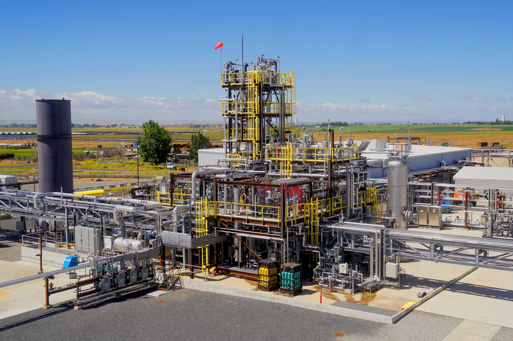
Vista is working closely with a technology provider who developed a proprietary carbon capture technology of flue gases. The carbon dioxide (CO2) product is to be compressed to the pipeline for sequestration, contributing to Canada’s emerging carbon capture, utilization and storage (CCUS) initiatives.
The project includes supporting the licensor in the development of essential engineering design and cost estimates.
The work includes:
- Plot plan – engineered drawings and 3D modelled plot plans
- Process flow diagram (PFD)
- Piping and instrumentation diagram (P&ID)
- Review and verification of utility requirements, including but not limited to water, steam, electrical loads, etc.
- Sized equipment list
- Total installed cost (TIC) estimate
Vista and another company worked collaboratively for the client to evaluate a carbon capture, utilization and storage (CCUS) facility concept that aims to treat flue gas emitted from once-through stream generators (OTSGs).
The team worked to define the basis of the proposed carbon capture project and determine the feasibility of an amine based CCUS facility.
The study established the following:
- Flue gas composition
- Operating temperatures and pressures
- Desired CO2 purity
- Carbon capture plant size and phasing
- Flue gas treatment redundancy
- Various amine technologies evaluation
The feasibility study included:
- Block Flow Diagram
- Process Flow Diagrams:
- Flue gas collection ducting
- Flue gas pre-treatment
- CO2 absorption, stripping, dehydration, and compression
- Material Balance Diagram and Stream Table
- Equipment List, including sizes, types, and services
- Preliminary General Layout drawings:
- Plot Plan
- General Arrangement showing the flue gas collection duct routing
- General Arrangement showing the flue gas processing facility
- Preliminary Utility Requirements
- Facility Interface List
- Fire Protection Philosophy
- Preliminary Electrical Study, confirming whether new loads can be accommodated by existing infrastructure
- Electrical Single Line DiagramA single line diagram is a simplified electrical drawing that represents a three-phase power system using one line to show the path of power…
- Preliminary Level 2 schedule
- Preliminary Cost Estimate support, including obtaining vendor budgetary proposals
Vista is working closely with the site EPC contractor to complete the power generation upgrades of an active potash mine to include 72MW of self-generation. Vista was brought in to assist in the project when the design work by other parties was struggling. The project is currently under construction.
The project has included:
- Complete modularization of pipe racks and electrical systems
- Balance of plant design and fabrication for the interconnected piping systems
Vista is working closely with a client who pursuing the development of a hydrogen (H2) based 120 MW power plant including power generation from gas-turbine generators (GTG).
The project may utilize components of steam methane reforming (SMR), along with carbon capture, utilization and storage (CCUS) affiliated with the power plant.
The study report and Vista’s scope included:
- Review of industry applications for proposed alternative fuel sources
- Determination of optimal hydrogen and natural gas blended feedstocks
- Evaluation of the feedstocks in the overall GTG system and subsystems
- Working closely with equipment suppliers to assess GTG viability with high H2 concentrations
- Evaluation of required equipment modifications to support high H2 input to the GTG
Vista supported an ongoing client with the creation of a technical specification to define the requirements for an enclosure for a customer supplied oxygen generator, including compressors, vessel, piping, HVAC and electrical systems. The system is to be utilized in a biogas upgrading to renewable natural gas (RNG) facility.
Coordinated with engineering disciplines to prepare a 3D model, P&ID and layout drawings for the enclosure and equipment contained within
The scope included:
- Preparation of a 3D model
- P&ID and layout drawings for the enclosure and equipment contained within
Vista supported an ongoing client with the procurement activities and engineering design review for a raw gas compressor package as part of a larger landfill gas (LFG) to renewable natural gas (RNG) upgrading project.
The scope included two 800hp single screw gas compressor skids and auxiliary equipment including high/low-pressure chiller skids and aerial coolers.
Vista successfully integrated the compressor packages into the client’s existing RNG upgrading systems.
Vista is working closely with a client to update their renewable natural gas (RNG) upgrading system P&IDs.
The scope included completing quality assurance (QA) checking of accuracy and consistency for the updated RNG P&IDs.
Vista also created the Chiller Package and an Evaporator P&ID by employing a collaborative approach between Vista, the client, and the equipment vendor engineering teams.
This program consisted of a dedicated project team that integrated closely with the client to oversee program governance and monitor critical success factors.
What started as a 20-person engineering team grew to a group of approximately 150 dedicated full-time employees within the first 18 months of the program. The role of this group was to perform facilities modifications projects and debottlenecking on a 30,000 BPD SAGD facility, as well as debottlenecking, expansion, and integration with an adjacent 118,000 BPD SAGD facility.
By operating multiple teams under one integrated program group, Vista was able to streamline engineering work and reduce costs.
This program structure enabled Vista to efficiently execute dozens of concurrent facility modifications and debottlenecking projects at the facility. The individual projects had a total installation cost (TIC) range between $0.3M to over $150M.
Example Projects within the Program
- Debottleneck (FEED, DE) for a 6,000 BPD expansion
- Debottleneck (Pre-FEED, FEED) for a ~15,000 BPD expansion
- Integration of the two SAGD processing facilities
- Artificial lift conversion to electrical submersible pump (ESP)
- Chemical injection control and emulsion measurement
- Adding a soda ash unit
- Adding shipping pump
- Replacing diluent with partial condensate
- Adding a BFW/BD heat exchanger
- Proposing a fire mitigation plan
- Blowdown water hammer
Vista completed detailed engineering design, procurement, and project management of a grassroots pilot SAGD thermal facility.
Scope Included
- 500 m3/day water treatment and steam generation system
- thermal production cooling and treating system
- produced/casing gas cooling and handling
- water separation, skimming, and disposal pumping system
- utilities including flare, instrument air, and fuel gas systems
As part of a significant project to upgrade a client’s two existing atmospheric treating batteries so as to ensure safe and continued operation of the facility for 15 years, Vista conducted the FEED and detailed engineering for a project to replace and extend a non-guyed Once-Through Steam Generator stack in order to address corrosion issues and to increase plum dispersion.
Vista designed a structural frame for a 42.4-metre (140-foot) stack to avoid the use of guy wires as well as the process to erect the structural steel within a building that had no structural or architectural drawings or plans. The stack was erected in a short time and required only a minimal amount of downtime for the facility.
Vista’s work on this replacement of an atmospheric treating train with a capacity of 1,800 m3/day emulsion, 1,500 m3/day dry crude included the following:
- Demolition of existing facilities
- Additional truck pit dump tank and new charge pump
- Wash and settling tanks with process building
- Two 3,000 barrel sales oil storage tanks
- Modifications to three truck pit dump tanks and three sales oil storage tanks
- Sales oil off-loading facility
- Tie-ins to existing facilities and utilities
Vista performed detailed engineering design, procurement, and project management for a pressure treating addition to an atmospheric treating facility.
- Truck pump off system to charge tank and treater feed pumps
- Pressure treaters designed for 1,625 m3/day emulsion feed rate and 1,300 m3/day sales oil
- Inlet emulsion/sales oil exchanger, sales oil cooler, produced water cooler
- Desand tank and tie-in to existing recycle tank and associated pumps
- Tie-ins to existing sales oil storage and water skimming tankage
- Utility systems: glycol cooling system serving process requirements, instrument air, fuel gas and flare
Excessive casing gas pressure within a client’s heavy oil production field was negatively impacting emulsion production. Vista was engaged to design a pipeline revision to alleviate casing gas backpressure at the wellheads. A portion of the existing above-ground pipeline infrastructure was looped. Approximately 600 metres of above-ground CSA pipeline was installed parallel to the existing line, starting at the drilling pad and terminating at the oil battery. Subsequent stress analysis was conducted.
Casing gas pressure at the wellheads was reduced by approximately 29 percent. Resulting increased emulsion production levels are still being analyzed.
Vista was engaged by its client to design a Cyclic Steam Stimulation pilot facility to inject steam and produce emulsion oil from one well at an existing battery. The pilot consists of a Once-Through Steam Generator (OTSG) complete with raw water filtering vessels and brine regenerated water softeners. An onsite steam generator produces 80-percent quality steam for injection into the wellhead.
Vista’s services included the engineering and procurement for emulsion handling, produced gas cooling and separation, process drain and pop tanks, water treatment waste and blowdown tanks, low-pressure flare system, propane fuel system, and electrical utilities. Engineering was also performed on the raw water and emulsion tanks supplied.
Vista’s client operates a large Steam Assisted Gravity Drainage project where inlet water chemistry to the warm lime softener was going to be changing as a result of using produced water/blowdown from the pilot plant in the short term, and future plans to use saline water as makeup for the water lime softener. Due to the change in salinity in the inlet water, the client’s water treatment specialists and coordinators identified the need to install a soda ash storage and delivery facility. Vista’s detailed engineering and procurement analysis recommended installing an automated soda ash storage and delivery system that is similar to the existing lime and MagOx packages.
The initial soda ash package (complete with foundation, structural supports, piping, electrical instrumentation and control system tie-ins), was initially purchased and completed by the client, using a template from another facility. The soda ash package vendor provided substandard engineering quality with insufficient and incorrect information on drawings and datasheets. Vista provided technical expertise and guidance to correct and update the vendor information to a level sufficient for construction. Vista then completed a drawing and data consolidation, redrafting the vendor drawings and creating new datasheets.
Vista’s attention to detail and expediting of the vendor skid limited the extent of delay and rework. With Vista’s experience in water treatment, the tie-in locations for feed water and soda ash slurry were optimized to enhance the effectiveness of the chemical addition.
Vista’s client constructed a Cyclic Steam Stimulation pilot project at an existing licensed cold production heavy oil field in northwest Alberta. The pilot facility is designed to produce a maximum 207 m3/day (1,300 barrels per day) of emulsion. The pilot facility will allow for temporary steam injection that will help evaluate the future enhanced oil recovery (EOR) potential in the client’s leases in the area.
Vista provided the Pre-FEED, FEED, detailed engineering and procurement services for the project, which included a 25 million BTU/hour Once-Through Steam Generator, water treatment, storage tanks, and tank treatment facilities. Vista’s previous experience and proven designs were used as templates to expedite the engineering for this client’s first heavy oil facility design.
Upgrades and expansions to a client’s existing heavy oil lease area that included both Steam Assisted Gravity Drainage and Cyclic Steam Stimulation facilities meant that the client’s current pumps would be inadequate to supply the required volumes of raw water for production.
Vista designed a new logic control system to improve overall operability between the main pumping station and smaller submersible pumps at various locations. Additionally, the water system’s single main booster pump was replaced with a series of upgraded pumps with the capacity to handle significantly higher discharge pressures and provide redundancy for improved reliability of the system.
This new system will adequately meet the requirements of the current production fields as well as for additional production from future facilities.
Vista carried out the comprehensive FEED, detailed design, procurement, and project management for a Steam Assisted Gravity Drainage (SAGD) pilot project near Lloydminster, Saskatchewan. The project’s prime purpose is to determine if SAGD was a viable technique for production within a particular heavy oil reservoir at that location.
As the pilot facility is being installed to confirm a method for designing a commercial-sized facility, the facility was designed to minimize capital expenditures at an increased operating cost. The anticipated life of the facility is 6 months to 2 years. A fit-for-purpose approach was adopted for this project to minimize capital expenditures in line with the limited operating life and the objective of the pilot plant, including the use of pre-existing equipment. As a result, many of the usual design criteria applicable to other SAGD projects did not apply to this project. Vista’s past experience with heavy oil projects was critical in being able to meet the client’s needs.
Vista is working with its client to develop a vertical steam drive pilot project near Peace River, Alberta. Started in late 2011, the project was completed by the end of 2013. The project is designed to produce approximately 4,800 barrels per day of emulsion and will be used to evaluate the potential for further heavy oil production at the client’s other locations in the area.
Because of its extensive heavy-oil expertise, Vista was sought out by its client to conduct the pre-FEED, FEED, detailed engineering, and procurement for the pads and pipelines for the project, including major components such as a 100-MMBtu/hr OTSG, water treatment, storage tanks, and a tank-treatment facility.
A Steam Assisted Gravity Drainage project north of Fort McMurray, Alberta, required additional heating capacity for a multi-phase expansion of water treatment plants. In Vista’s FEED design process, it was determined that winter start-up conditions would require additional heating capacity beyond what was available with the currently installed 17.6 GJ /hour glycol heaters.
It was determined that the facility required 50 GJ/hour for the expansion. Two 33 GJ/hour heaters were installed to provide sufficient heat for building heating, heat tracing, tank/vessel heating, and fuel gas heating. The need for construction to coincide with winter start-up required the project to be fast-tracked, with detailed engineering completed and equipment sourced much sooner than would normally be expected. Vista was able to meet and exceed the client’s requirements and is currently favored for future projects of a similar nature.
A client’s SAGD project was not achieving nameplate oil production due to a lack of steam capacity. Vista was asked to evaluate the implementation of the required changes to allow additional steam to be injected into the current reservoir in order to achieve planned oil production.
Working within an operational project and other brownfield scenarios can pose challenges in the engineering and evaluation processes as available drawings and plans are often not up-to-date. Vista was able to provide a comprehensive evaluation and cost estimate to remediate the steam capacity issue in a relatively short period of time and under budget. Vista’s proposal included adapting a new design into an existing plant whereby the post debottleneck operation will have a new capacity to recycle wastewater, thereby lessening the environmental impact of the project.
Vista worked with its client to design an alkaline surfactant polymer (ASP) injection pilot facility for use in the client’s Bakken oil production zone in southern Saskatchewan.
The project’s design specifications called for an injection capacity of up to 800 m3/day of the polymer. Vista conducted the pre-FEED, FEED, and procurement for the project within specified timelines and budgets.
The ASP package was comprised of:
- two SNF skids and an alkaline silo, used to mix, blend and inject surfactant, alkaline (soda ash), and polymer
- a source-water treatment system for hardness removal
- tanks for raw water, soft water, surfactant and wastewater
- source water pipeline from the source water well to the ASP facility
- four individual polymer injection pipelines from the ASP facility to four injection wells
In order to convert existing facilities and infrastructure associated with the existing waterflood to a miscible flood, the client chose Vista to complete the design of a buried pipeline and ancillary facilities including 39 km of pipe, pipeline risers, new piping headers, and meter stations.
Pipe of the required specification and quantity for this project generally takes six months or more to fabricate and coat, depending on mill availability. However, the project timeline required the pipe within two to three months. In addition to time constraints as a result of a fast-approaching end to the winter muskeg construction season, pipe mills were reluctant to produce a small quantity of such specialized pipe.
Vista was able to meet all of these challenges and successfully secured all the materials in a timeframe that allowed the project to proceed in accordance with the client’s schedule.
Vista conducted the engineering and procurement work for a client who was expanding its polymer injection from the pilot phase to a commercial operation. The project required approximately 900 m3/day of polymer injection to nine injection wells located at 2 separate pad locations. Major equipment for the project included:
- polymer hydration skid
- water treatment facility
- various 2,000-barrel water tanks
- MCC expansion
- polymer injection skid
A Fiberspar pipeline of approximately 500 metres in length was constructed to bring polymer to a five-pump injection skid at one pad site for 5 injection wells at that location. Water for the hydration process will come from source water wells. The use of produced water from one of the client’s batteries required the installation of 2 pumps at the battery location to transport water to the polymer hydration skid via 5,000 metres of new pipeline
Through extensive consultation with vendors and our clients, Vista has designed a novel water reuse system in which blowdown from a once-through steam generator (OTSG) is used as the feedstock for a secondary OTSG.
After the successful implementation of this high-value design, steam production was drastically increased while wastewater (boiler blowdown) was reduced by 75%.
This system resulted in a substantial net reduction of water usage by the facility.
Vista’s thorough understanding of wastewater chemistry has led to the successful implementation of wastewater reuse systems.
In these detailed systems, recycled water and wastewater chemistry are objectively reviewed and decisions are based upon the specific defined components requiring treatment.
In some applications, Vista has identified locations where the blending of wastewater and recycled water meets the downstream requirements. This has resulted in a reduction of water treatment equipment.
The reduced water treatment equipment significantly lowers capital cost and operating costs for the facility.
Vista has extensive experience in the operation of filters and ion exchange equipment.
By leveraging our knowledge with different equipment suppliers and operating facilities, we successfully revised filtration and ion exchange regeneration sequences, which limited the quantity of wastewater generated.
In addition, Vista has been involved in the successful design of a novel chemical reuse program, wherein caustic from a weak acid cation (WAC) exchanger is partially reused for several sequential regenerations.
This design led to a reduction in operating costs by decreasing the total chemical and water consumption requirements for ion exchange regeneration.
In systems where RLD is required, Vista has investigated the implementation of mechanical vapor compression evaporators, crystallizers, and thermosyphon reboilers.
Implementation of these systems enabled the plant to meet the stringent regulatory demands of the jurisdiction.
Vista has implemented a wide variety of water treatment technologies as part of our water management systems.
- Solids Settling
- Filtration
- Lime Softening
- Ion Exchange
- Iron & Manganese Removal
- Induced Gas / Static Flotation
Vista has expertise treating water systems with oil and grease, silica, permanent & temporary hardness, suspended solids, iron, multivalent cations, oxygen, and microbiological contaminants.
Vista was contracted to investigate existing and new technologies to reduce the wastewater volumes at a water treatment and steam generation plant.
A changing regulatory environment and lack of access to a sufficiently sized disposal system were causing the client to explore new water reduction possibilities.
Vista investigated a wide variety of RLD technologies, as well as zero liquid discharge (ZLD) technologies, and formulated 21 process arrangements to find the most cost-effective option.
Our work included:
- technology investigations
- laboratory test design
- water analysis
- bench-scale testing
- capital and operating cost determinations to reach a technology arrangement that was optimized for the client
Clients have trusted Vista with their technology selection for major, industrial water management facilities.
These projects considered site-specific water availability and environmental and disposal conditions while ensuring the plant met the area’s regulatory requirements. The technology was recommended based on technical merit, as well as the capital and operating cost considerations.
Many of Vista’s industry-leading cost innovations were considered, including piping and equipment modularization, plot plan optimizations, and our data-centric approach to engineering.
Vista performed the front-end engineering design (FEED) and detailed engineering (DE) for a cogeneration facility. The facility featured gas turbine generators (GTGs) followed by heat recovery steam generators (HRSGs) designed for site power production, as well as the steam generation required to stimulate a thermal reservoir.
Scope Included:
- Two 50 MW General Electric LM6000PH gas turbines driving 13.8kV two-pole brushless generators
- Waste heat from the turbine exhaust was used to produce up to 356,000 kg/hr of 10,000 kPag steam in two HRSGs
Vista performed the front-end engineering design (FEED) and detailed engineering for the addition of a gas turbine to a once-through steam generator (OTSG) at a large-scale SAGD processing facility.
The engineering design allowed for a Solar Taurus 70 gas turbine to be mated to an OTSG producing up to 167,600 kg/hr of 9,600 kPag steam.
Class-5 cost estimate for a cogeneration facility including two Solar Mars 100 gas turbines, each followed by a hybrid once-through steam generator (H-OTSG) capable of firing on:
- fuel gas
- gas turbine exhaust gas
- a mixture of both
The design would provide a stable steam generation under a fluctuating gas turbine load.
This was for a cogeneration utility plant located within an in-situ heavy oil facility. Deliverables included a Class 5 estimate for complete engineering and construction.
Vista performed the front-end engineering design (FEED) of a cogeneration facility featuring gas turbines (GTs) followed by hybrid once-through-steam-generators (H-OTSG) designed for site power production, as well as the steam generation required to stimulate a thermal reservoir.
Scope Included:
- Three x 11.3 MW Solar Mars 100 turbines or two x 15 MW Solar Titan 130 turbines and OTSGs
- Each turbine exhausts into an OTSG burner to provide 320 MMBTU/hr of heat and generates 149,000 kg/hr of steam at 9,900 kPag
Vista performed the detailed engineering design and procurement of a gas processing facility handling 25 MMSCFD (708 103 Std. m3/day) of natural gas, to reduce the carbon dioxide (CO2) content to a pipeline specification level.
The gas plant features:
- Inlet separation
- Amine plant (MDEA based)
- Storage tankage for water and amine
- Electrical power generation
- Modifications to instrument air and heat medium system
- Project also included the tie-in of several wells feeding the gas plant. Wellsite facilities included choke-heaters, string heat facilities (heater coil and string heat pump) dehydrator, and flare facilities.
Vista completed the detailed engineering design and procurement of a grassroots gas processing facility handling 20 MMSCFD (566 103 Std. m3/day) of sweet natural gas. The project was completed on a very fast track schedule (kick-off to commissioning took just over 4 months).
The project also included the tie-in of several wells feeding the gas plant. Wellsite facilities included choke-heaters, string heat facilities (heater coil and string heat pump) dehydrator, and flare facilities.
The gas plant features:
- Inlet separation, gas dehydration/chilling, and de-ethanization of recovered liquids
- Propane refrigeration system
- Residue gas compression
- C3+ liquids storage and pipeline pumping
- SCADA communication with gas wells supplying the facility
- Produced water separation and storage facilities
- Utility systems: instrument air, fuel gas, and flare
- Control room and electrical distribution
Vista performed the detailed engineering design and procurement of a gas processing facility addition handling 28 MMSCFD (793 103 Std. m3/day) of sweet HP natural gas, to improve recovery of liquids from a gas cycling scheme.
The gas plant features:
- Gas dehydration/chilling for recovery of liquids
- Propane refrigeration system
- Recycle gas compression modifications
- Upgrade of existing salt bath heater
- Control system upgrade to PC based MMI
- Control room and electrical distribution modifications
Vista has engineered large-scale gas handling systems integrated into one of the province’s largest SAGD developments for a foremost Alberta producer. This project involves a major facility processing 30 MMSCFD of gas each day, requiring an array of gas-handling equipment including:
- Vapour recovery unit (VRU) compressors
- Liquid ring compressors
- H2S scavenger units
- Tie-ins and interconnecting piping
The gas-handling equipment at this facility is integrated into the once-through steam generator (OTSG) process.
Vista designed and installed gas sweetening packages to treat all produced gas for use as fuel for the OTSGs.
As the lead EP contractor for this multiphase project, Vista was able to apply key lessons throughout multiple expansion phases, increasing modularization and templated designs. These advantages saved field installation time, reduced total installed costs, and provided sparing, operational and maintenance efficiencies.
Key success factors include the following:
- Partnership model approach to a long-term relationship with the producer
- Integrated project team able to jointly develop best practices
- Key learnings and efficiencies applied throughout multiple expansion phases
- While Vista’s prime focus with the client was engineering SAGD facilities, the team leveraged Vista’s extensive gas plant experience to ensure smooth project execution
- Dedicated team capable of ramping up to 400+ people as required
Vista has been working with this client for nearly 15 years, engineering small projects for several major gas facilities.
Work started as a study to help address catastrophic corrosion issues associated with a change in amine (which was solved by changing the amine to Sulfinol) and has led to a long series of gas plant modifications and revamps.
Typical work included:
- Engineering plant modifications associated with amine upgrade including new vessels, exchangers, tower internals, pump modifications, and associated piping/instrumentation and EIC work;
- Replacing sweetening solvent with Sulfinol;
- Engineering a sulphur degassing facility;
- Installing a sales gas compressor;
- Engineering a variety of piping changes, equipment replacement/repairs required for shutdowns;
- Engineering a 1000 HP multistage centrifugal amine charge pump installation with electric driver;
- Engineering the removal of a failing sulphur pit roof and replacement with new concrete panels without downtime
- Engineering associated with installing several lube oil coalescers, piping changes, PSV evaluation/replacement, revamp of fire & gas detection systems.
Key success factors contributing to this long-term partnership:
- Projects have been managed by a Vista Project Manager who is also an owner of Vista;
- Key people who engineered projects remained with the same jobs over the years;
- Rather than a traditional discipline-based specialisation, engineers from the Vista “Small Projects Team” multi-tasked to achieve quick turn-around on engineering;
- Working directly/closely with plant operations & maintenance teams and quickly accommodating their needs resulted in minimising downtime/lost production;
- Vista’s diverse experience and repository of past similar engineering solutions allowed selection of tried and tested solutions that worked every time
Vista was engaged by a client who had purchased an existing battery and associated wells and pipelines in northwestern Alberta. The existing sour gas pipelines ran to a processing facility owned and operated by a third party. Vista’s client wished to reduce its operating costs and optimize its asset utilization by re-routing its produced sour gas to a facility that it owns and operates for processing.
Vista conducted the detailed engineering and procurement for the project for the installation of all necessary infrastructure and facilities associated with the new pipelines. Vista’s experience with pipeline projects allowed this project to be expedited in order to proceed with installation in muskeg prior to the end of the winter construction season.
Vista worked with its client to design the equipment and systems for a 4-pad, toe-to-heel-air-injection (THAI) in-situ heavy oil recovery project near Conklin, Alberta.
The 10,000 barrel per day project included 5 well-pairs for each of the 4 pads and an additional pad with cooling and oil/water separation and air/steam production.
Vista provided comprehensive FEED services as well as project management, quality surveillance, construction management and commissioning and start-up assistance. Vista also managed contractor bidding, cost control and scheduling requirements for the project.
This project involved the engineering design of pads and pipelines for a commercial-scale facility incorporating proprietary toe-to-heel air injection (THAI) technology utilized in an in-situ pilot plant. Of special interest in terms of pipeline design was the challenge of handling large volumes of sand entrained in the emulsion: Vista ensured that a delicate balance was reached to keep liquid velocities low enough to avoid pipeline erosion, yet high enough to avoid sand deposition.
The project’s focus was the engineering design of four pads with five well pairs each, complete with wellhead separators. Two of the pads acted as accumulation points for oil emulsion and also accommodated other equipment, including air compressors, tanks, glycol heaters and steam generation equipment.
Aboveground pipelines connecting the new pads to the central processing facility (CPF) included a 20″ sour gas line, a 6″ sour oil emulsion line, a 6″ produced water line, a 12″ high-pressure air line, a 6″ boiler feedwater line, a 4″ fuel gas line and a 4″ recovered condensate line. An existing 3″ fuel pipeline located under one of the new pad sites required Vista to reroute the existing line.
This existing pipeline was located under the new pad site, and commercial expansion plans posed a risk of long-term service interruption for the facility. In response, Vista rerouted the existing pipeline away from the new pad site, enabling the facility to maintain production levels while the new steel pipeline was tied in from the connection point to the rack piping.
In order to convert existing facilities and infrastructure associated with the existing waterflood to a miscible flood, the client chose Vista to complete the design of a buried pipeline and ancillary facilities including 39 km of pipe, pipeline risers, new piping headers, and meter stations.
Pipe of the required specification and quantity for this project generally takes six months or more to fabricate and coat, depending on mill availability. However, the project timeline required the pipe within two to three months. In addition to time constraints as a result of a fast-approaching end to the winter muskeg construction season, pipe mills were reluctant to produce a small quantity of such specialized pipe.
Vista was able to meet all of these challenges and successfully secured all the materials in a timeframe that allowed the project to proceed in accordance with the client’s schedule.
Vista conducted the engineering and procurement work for a client who was expanding its polymer injection from the pilot phase to a commercial operation. The project required approximately 900 m3/day of polymer injection to nine injection wells located at 2 separate pad locations.
Major equipment for the project included polymer hydration skid, water treatment facility, various 2,000-barrel water tanks, MCC expansion, and polymer injection skid. A Fiberspar pipeline of approximately 500 metres in length was constructed to bring polymer to a five-pump injection skid at one pad site for 5 injection wells at that location. Water for the hydration process will come from source water wells. The use of produced water from one of the client’s batteries required the installation of 2 pumps at the battery location to transport water to the polymer hydration skid via 5,000 metres of new pipeline.
As part of a long-term partnership with this client, Vista completed the detailed engineering design and procurement of a $3.5 million grassroots heavy oil treating battery processing 2,700-4,000 barrels of oil per day (BPD) or 430 – 635 m3/day of 15 API oil, featuring:
- Production manifold and test treated
- Direct fired treater with desand system
- Inlet emulsion/sales oil exchanger and sales oil tankage with pipeline tie-in
- Produced water skimming, filtration and water reinjection pumping facilities
- Desand and recycle tankage and associated pumps
- Utility systems: glycol heating system serving both process and utility requirements, instrument air, fuel gas and flare
Vista also completed the detailed engineering design and procurement for the battery’s free-water knock-out (FWKO), test treater, and production satellite. The project was needed for this heavy oil battery expansion to handle 5,000 BPD or 800 m3/d of oil and 20,000 BPD or 3,200 m3/day of water, featuring:
- Direct fired FWKO vessel with desand system
- Direct fired test treater sized for 60 m3/d oil and 150 m3/d water
- Produced gas cooler
- Inlet manifold extension
- Remote satellite manifold
As part of a long-term partnership with this client, Vista completed the detailed engineering design of a grassroots heavy oil treating battery processing 4,000 barrels of oil per day (BPD) or 635 m3/day of 15 API oil, featuring:
- Production manifold
- Two test treaters
- Direct fired treater with desand system
- Inlet emulsion/sales oil exchanger and sales oil tankage with truck loading
- Produced water cooling, skimming, filtration, and water reinjection pumping
- Desand and recycle tankage and associated pumps
- Glycol heating system serving both process and utility requirements
- Onsite generation of electrical power (480v, 3ph, 60hz)
- Fuel and flare utility systems
Vista was also engaged to complete detailed engineering design and procurement of multiple battery expansions to this facility including the addition of:
- a pressurized FWKO to increase water handling capacity to 10,000 BPD or 1,590 m3/day, as well as a produced gas dehydration system and an instrument air package;
- a second 6,000 BPD or 950 m3/day water disposal pump with filter and booster pump, as well as a second oil emulsion inlet manifold
Vista completed the detailed engineering design for a grassroots heavy oil treating battery processing up to 1,900 BPD (300 m3/day) of 18 API oil, featuring:
- Production manifold with pig receiver
- Indirect fired test heater and test separator
- Direct fired treater with chemical injection
- Sales oil storage tankage with pipeline tie-in
- Produced water skimming, filtration, and water injection pumping facilities handling 600 m3/day
- Recycle tankage and pumps
- Sour produced gas compression (40 103 m3/day)
- Utility systems: glycol heating system, instrument air, fuel gas and flare
In order to optimize the steam generation and fuel and power usage at a client’s in-situ toe-to-heel air injection (THAI) project, Vista undertook a study to evaluate the potential for combustion of low-BTU gas in the project’s on-site turbine.
The project was completed on time and on budget between February and July 2009.
Vista performed the detailed engineering design for a client planning to drill additional production wells at an existing conventional oil battery. Vista was contracted to design the emulsion tanks and related gas and fluid treatment and handling processes, as well as the piping from the production wellhead to the on-site tank farm.
The project was designed to meet the client capacity specifications of 300 m3/day of sour oil production as well as produced gas. The test and production tanks required 4-day production storage capacity.
As part of a long-term relationship with this client, Vista completed engineering studies, pre-FEED, FEED and detailed engineering design for a grassroots oil treating battery initially processing 3,000 barrels of oil per day (BPD) or 412 m3/day.
Vista was also engaged to perform subsequent expansion work to increase the production rate to 15,000 BDP or 2,060 m3/day. Features included:
- Production manifold and test tank
- FWKO and direct fired treaters with desand systems
- Inlet emulsion/sales oil exchanger, sales oil cooler, produced water cooler
- Coalescing tank and sales oil storage tanks with future pipeline tie-in
- Produced water skimming, filtration and water reinjection pumping facilities
- Desand and recycle tankage and associated pumps
- Utility systems: glycol heating system (process & utility) glycol cooling system for produced gas cooling, instrument air, fuel gas, and flare
- Steam expansion – grassroots thermal steam generation facility with water treatment system, three 50 MM BTU/hr steamers, steam distribution system to 15 wells, and thermal production gathering system complete with manifold and test separator
Vista was engaged to evaluate the impact of new process conditions related to the implementation of condensate blending on the performance of a major facility’s oil treating equipment. Vista’s scope of analysis included evaluating the operation of the vapour recovery unit (VRU).
Included in the project execution was the development of new datasheets for key equipment and units (including free water knock-out drums, treaters and VRU). An investigation was also performed into the adequacy of existing utilities and infrastructure and required tie-ins. Vista also updated process flow diagrams (PFDs) and piping and instrumentation diagrams (P&IDs) for the facility.
Vista executed the Detailed Engineering phase of a project to analyze, select and install a dual viscometer in a sales oil line to resolve off-specification product blending problems. The scope of design encompassed the power supply and electrical tie-ins including EHT on process piping, piling design to support skids, as well as associated piping and appurtenances. The plot plan layout and area classifications were also updated.
Vista’s design improved the blending ratio accuracy, increased the reliability and operability of equipment, and significantly reduced maintenance requirements. All of these successes contributed to streamlined operations and lower overall facility operating costs.
Vista engineered the mechanical and electrical elements of truck loading and unloading systems at a station capable of accommodating five trucks in simultaneous operation. The scope of the project included five truck bays (with provision for two additional), a control shack, interconnecting pipe racks and piping.
Vista met the client’s cost-effectiveness expectations by, where possible, using designs from the existing central processing facility (CPF), such as the pipe rack structure. Also per the existing CPF, Vista followed a modular design concept with use of identical process equipment and systems.
Vista provided full-scale EP capabilities with a project team including project management, project controls, document control, as well as process, mechanical, piping/drafting, civil/structural, electrical and instrumentation disciplines.
Vista performed the Pre-FEED, FEED and Detailed Engineering phases of a project to resolve process issues related to preparing product to meet pipeline specifications at a major SAGD facility. A change in diluent from naphtha to Southern Light Diluent resulted in true vapour pressure (TVP) problems in the process equipment, which Vista was called in to investigate and mitigate.
The project entailed significant operational, economic and environmental risks. These factors drove stringent schedule, budget, safety and quality targets for the project, all of which were exceeded by Vista. Additionally, the client benefitted significantly by Vista’s implementation of value improvement practices (VIPs) in technology selection, process simplification and waste minimization.
Vista performed the detailed engineering design of an asphalt storage facility with transfer stations. The facility included:
- two 64,000 barrel asphalt storage tanks
- four truck off-load and two truck load-out stations
- associated pumps and piping systems
The design also included a hot oil heating system for tank heating and heat tracing. Facility Design Requirements:
- Truck unload temperature – min. / max. 290°F / 320°F
- Tank maintain temperature during summer – min. / max. 220°F / 310°F
- Truck load temperature – min. / max. 290°F / 315°F
- Normal and maximum hot oil temperatures.400°F / 460°F
Project Experience
Overview
Need a take away? Download our project experience.
Case Studies & Expanded Profiles


Improve your project success with the help of seasoned experts

Tyler Elchuk
Business Development Director