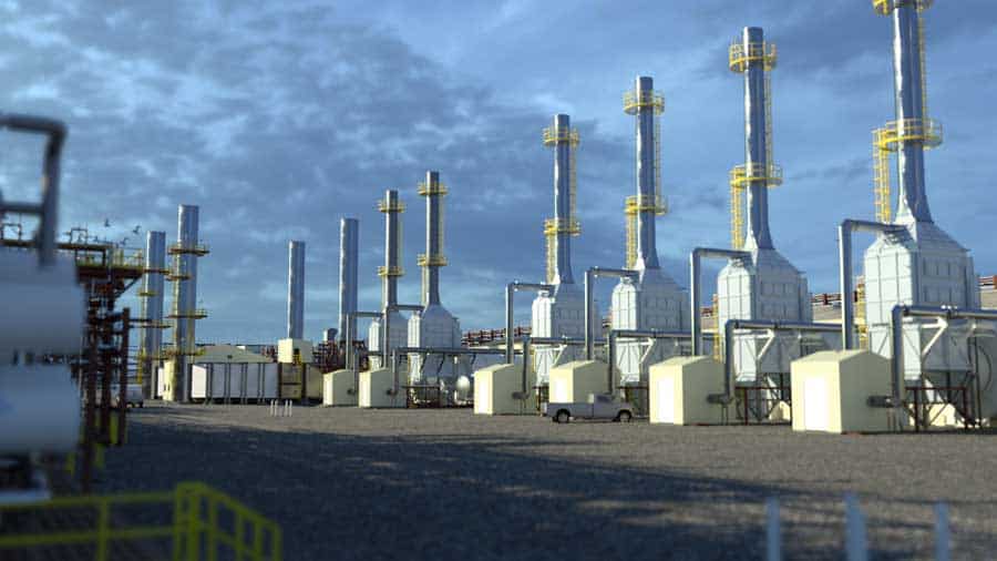
Economical in-situ thermal technology has been long sought after in the petroleum extraction industry.
To supplement conventional oil production, many producers have shifted their focus to unconventional oil. One example of this resource is the bitumen present in Canada’s oil sands, but Canada is not the only bitumen-rich country in the world.
Over 30 countries are known to possess recoverable heavy oil, including Venezuela, Saudi Arabia, and the United States.
In Canada, 80% of the heavy oil and bitumen present cannot be extracted through regular surface mining methods. Due to its highly viscous nature, heavy oil and bitumen cannot flow naturally to the wells that are drilled without being heated.
In pursuit of these resources, extensive research has been done, which has led to the discovery of many innovative thermal technologies over the years.
Table of Contents
In-situ Combustion
Variations of In-situ Combustion Technology
» Toe-to-Heel Air Injection (THAI)
» Catalytic Upgrading Process In-situ (CAPRI)
» Steamflooding
» Cyclic Steam Stimulation (CSS)
» Steam-Assisted Gravity Drainage (SAGD)
Variations of SAGD Technology
» Vapour-Assisted Petroleum Extraction (VAPEX)
» Solvent-Assisted Steam-Assisted Gravity Drainage (SA-SAGD)
» Steam and Gas Push (SAGP)
» Electromagnetic (EM) Heating
3 Methods for Electromagnetic Heating
» Downhole Electric Heaters
» Radio Frequency (RF) Heating
» Electric Resistive Heating
In-situ Thermal Technology Recap
Reserves that were previously considered inaccessible are now bringing thousands of barrels of heavy oil and bitumen to the surface every day. From steam flooding to in-situ combustion, to electromagnetism, a brief look into the history of in-situ thermal technology shows just how far the industry has come.
In-situ Combustion
In-situ combustion is the oldest of all the thermal enhanced oil recovery (EOR) technologies. Adopted in the 1920s, many operators have deemed it an unsuitable method for oil recovery because of the number of failed operations when it was first being tested. Operators struggled to control which way the fire burned. However, advancements in this in-situ thermal technology indicate that higher recovery rates can be reached in certain formations, with proper engineering practices in place.
In this process, an injection well and a production well are drilled. In-situ combustion requires the injection of a gas to start a fire within the reservoir. The fire burns through roughly 10% of the oil in place as it makes its way towards the production well and to keep the fire burning, air is injected into the reservoir. The burning oil also leaves behind a coke residue, which further fuels the fire. The oil is pushed towards the production well by the combusted gases and the water within the formation.
The two methods for in-situ combustion are forward and reverse. During forward combustion, the fire advances in the direction of the air flow. In reverse combustion, the fire travels in the direction that is opposite to the air flow. Forward combustion is the more popular method and it can be further defined by its “wet” or “dry” process.
When dry forward combustion takes place, only air is injected into the reservoir to keep the fire burning. In wet forward combustion, both water and air are injected into the reservoir. The water vaporizes into steam when it reaches the reservoir, due to its high temperature. The steam travels ahead of the fire and lowers the viscosity of the oil. This increases the speed of the process.
Variations of In-situ Combustion Technology
Let’s look at the various ways in-situ thermal technology uses combustion.
Toe-to-Heel Air Injection (THAI)
THAI technology was developed by Malcolm Greaves in late 1990s. It was first field tested in the Athabasca Whitesands in Canada from 2006-2011 and its recovery rates are between 70% and 80%.
For this method, a horizontal production well is drilled, and a vertical well is drilled at its toe. Steam is injected into the vertical well to heat the surrounding area. Afterward, the air is injected and a fire is ignited. Injection of air continues to fuel the fire and it moves toward the heel of the horizontal well. As it burns, it heats the oil in place and allows it to drain into the horizontal production well.
Catalytic Upgrading Process In-situ (CAPRI)
The CAPRI method was invented in 1998. Recovery rates are between 70% and 80%.
Considered the catalytic extension of THAI, CAPRI uses the same well setup and air injection methods. However, the difference is that hydro-treating catalysts are packed around the horizontal production well. This ensures that oil passing through the well is upgraded in-situ. The benefit to this technique is that less upgrading of the oil is required above the surface, which makes the process more cost-efficient.
Steamflooding
Steamflooding started in 1952, when Shell Oil Co. did a steam drive pilot in the Yorba Linda field of California. By the late 1970’s, it had become a commonly used technology in California. Recovery rates are usually between 50% and 60%.
In a traditional steamflood, several vertical wells are drilled. Some of the wells are injectors and some are producers. Steam, generally with a quality of 80% (80% vapour, 20% liquid) is injected into the formation and it heats up the surrounding oil. As the steam travels further from the injection wells, it condenses into hot water. The hot water helps the oil to expand and it provides a driving force on it. This makes it easier for the oil to travel to the producing well.
Similar to steamflooding is the hot water drive method. Instead of steam being injected into the reservoir, hot water is injected instead. It lowers the viscosity of the oil and pushes it towards the production well. This process is more cost-efficient, but it is better suited for producing lighter oil.
Cyclic Steam Stimulation (CSS)
Cyclic steam stimulation, also called “Huff n’ Puff”, was discovered by accident in Eastern Venezuela in 1959. It was developed throughout the 1960’s and 1970’s and it became a commercially viable thermal in-situ technology in 1979. Expected recovery rates are from 10% to 40%.
CSS requires the drilling of one well that both injects steam and produces heavy oil and bitumen. The process has 3 stages: injection, soaking and production. The injection stage involves the injection of steam into the reservoir for several weeks. The steam is then allowed to “soak” into the reservoir. Soaking time can vary from a few days to several weeks as the steam heats the oil to make it less viscous.
Finally, the oil can flow to the well, where it is pumped to surface. This cycle is repeated until it is no longer profitable to do so.
Steam-Assisted Gravity Drainage (SAGD)
In 1978, Roger Butler, a chemical engineer working with Imperial Oil, had the idea for SAGD technology. In 1987, it was tested underground for the first time by the Alberta Oil Sands Technology and Research Authority (AOSTRA). SAGD technology became commercialized in 2001 by Cenovus Energy at Foster Creek. With oil recovery rates of up to 40-60%, it has become an aggressive competitor in the field of in-situ thermal technology.
SAGD requires the drilling of a horizontal injection well, and a horizontal production well approximately 5m below it. Steam is continuously injected into the reservoir through the injection well and it heats the surrounding oil and bitumen. As the viscosity of the oil decreases, its mobility increases and it flows downward to the production well. It is then pumped to the surface.
Variations of SAGD Technology
There are many SAGD variations within in-situ thermal technology.
Vapour-Assisted Petroleum Extraction (VAPEX)
This variation of SAGD was introduced by Roger Butler in 1991. The recovery rates for this process can be up to 80%.
VAPEX technology is similar to SAGD, except that a solvent in vapour form is injected into the reservoir. The solvent can be methane, ethane and/or propane. The solvent dissolves into the heavy oil or bitumen and the mixture drains towards the production well. Once it is brought to surface, the solvent is stripped from the oil and recycled back into the injection well.
Did you know?
 Facilities engineered by Vista produce about 1/3 of Alberta’s total SAGD production.
Solvent-Assisted Steam-Assisted Gravity Drainage (SA-SAGD)
An SA-SAGD pilot project for this method was first conducted by Imperial Oil in Cold Lake, Alberta in 2006. In this process, steam is injected into the reservoir, but it is mixed with 5% to 20% by volume of hydrocarbon solvent. Like VAPEX technology, the solvent dissolves into the heavy oil or bitumen, and helps it move to the production well. The use of solvents lowers the amount of steam required.
Steam and Gas Push (SAGP)
SAGP was created in 1997 by Roger Butler and his research group.
The SAGP method involves the injection of a non-condensable gas into the reservoir, in combination with steam. The gas lingers at the top of the steam chamber and it helps to preserve the heat that the steam generates. This reduces the amount of steam required and it increases the efficiency of the system.
Electromagnetic (EM) Heating
The earliest field tests for electromagnetic heating were done in the Ishimbayskoye Oil Field in Russia in 1969. They were ultimately unsuccessful due to the high cost and technological difficulties, so many companies lost interest. However, a desire to lower the environmental impact made from producing oil, and advancements in technology have led to a renewed interest in electromagnetic heating. Although it is not yet considered a commercially viable method for in-situ thermal operations, it shows promise for the future.
EM heating can be used in the reservoirs that would otherwise be unattractive for steam injection methods. This includes reservoirs that are thin, shallow, heterogeneous, fractured, have a high water saturation, and/or do not have a caprock. It can also be used to pre-heat the reservoir before steam is injected. This increases the efficiency of the process and it lowers the amount of steam required.
3 Methods for Electromagnetic Heating
In-situ thermal technology includes three methods for electromagnetic heating.
Downhole Electric Heaters
The idea for using electric heaters was first considered in the 1940’s.
The simplest way of applying heat electrically is to lower electric heaters downhole. The heater is placed in direct contact with the formation and it uses thermal conduction to release heat. Unfortunately, when using electric heaters, it can take a long time to heat the formation and the heat is not spread uniformly. Therefore many companies do not consider it to be a viable option in in-situ thermal operations.
Radio Frequency (RF) Heating
The concept of RF heating in-situ was first introduced in the 1970’s.
RF heating involves putting a large antenna into the ground, where it emits an electromagnetic field. The field is then converted into heat, which is used to lower the viscosity of the surrounding oil. Wells used to collect the oil can be either vertical or horizontal. An advantage to this method is that as it vaporizes the water surrounding the antenna into steam, the electromagnetic field reaches further into the reservoir and heats a different area.
Electric Resistive Heating
The first application of electric resistive heating in-situ was in 1981.
In this process, two electrodes are placed inside the wells that are drilled. They are connected to an AC source and a current is run through them. The water in the formation acts as a conductor and the electrical energy turns into heat. This process works best if many wells are drilled, because the heat generated is highest around the wells, and it decreases as the distance from them increases.
In-situ Thermal Technology Recap
A look at the history of in-situ thermal technology shows that oil companies are always exploring new ways to access the resources that were otherwise considered inaccessible. These technologies have helped to improve the efficiency of projects while lowering the cost and increasing production. Even with the dramatic increase in recovery rates from the first technologies implemented to where the industry is today, research is ongoing, and improvements will continue to be made. The oil industry shows no signs of slowing its quest for innovation anytime soon.