Carbon Capture and Storage (CCS) has become top of mind in oil and gas, energy policy, and sustainability conversations worldwide. But few, apart from the geologists and engineers who work directly in CCS, understand what it is.
This article will be the third of our series on “What Is CSS” and will serve as an introduction to CCS geology and reservoir engineering so that it can be understood by everyone.
CCS is a broad term that represents several technologies which capture carbon dioxide (CO2) emissions from facilities or directly from the atmosphere. The process is designed to help prevent the accumulation of greenhouse gases in the atmosphere to reduce global warming. Once captured, the CO2 is re-used as a gas in manufacturing processes or is stored via enhanced oil recovery.
There is growing interest in the application of carbon capture and storage technologies to help reduce greenhouse gas emissions in Canada and around the world.
Geology and Reservoir Engineering With CCUS
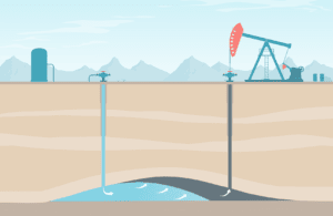
Carbon Capture and Storage (CCS), also known as Carbon Capture Utilisation and Storage (CCUS), is the process of capturing CO2 from a large source, transporting it and storing it underground. Site screening is one of the first steps to evaluate and find geological formations that have the potential for CO2 utilisation and storage. Geological interpretations and modelling can define storage attributes, qualify the storage site and help reduce the risk of CO2 release into the atmosphere.
The CO2 can be trapped by various formation/reservoir mechanisms when using carbon capture and storage. These mechanisms occur in sequence as the CO2 is injected:
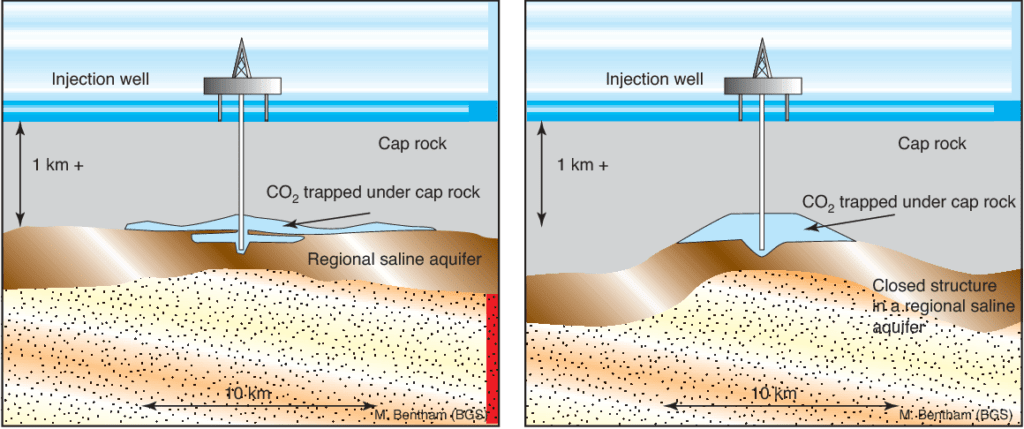
Structural Trapping
- CO2 trapped by subsurface geologic structures and confined by an impermeable cap rock is the primary trapping mechanism. The supercritical CO2 (denser than a gas, lighter than liquid) is injected into the pore space and will trickle up through the porous rocks to the top of the formation. It is then confined by an impermeable rock layer, thereby preventing leaks and vertical migration of CO2 into overlying formations.
Residual Trapping
- CO2 is further trapped because of the relative subsurface permeability and capillary pressure of the rock within the reservoir. The reservoir acts like a rigid sponge into which the supercritical CO2 is absorbed, displacing fluid left in the porous rock, and leaving behind CO2 residuals (I.e., CO2 droplets in the pore spaces).
Solubility Trapping
- Just as salts dissolve in water, CO2 dissolves in the aqueous phase of injection. CO2 dissolves in a salt brine in both its gaseous and supercritical state. Saltwater, now rich in CO2, is denser than the reservoir fluids and will sink over time to the bottom of the reservoir.
Mineral Trapping
- CO2 reacts with the reservoir rock and minerals during absorption. The CO2 first dissolves in water forming a weak carbonic acid. Over time, the weak acid will react with the rock and form solid carbonate minerals.
Deep Saline Aquifers
Deep saline aquifers have the largest estimated capacity for CO2 sequestration. The gas injection phase can often last 10 years or more, depending on the size of the project.
In the first phase the CO2 displaces the brine already present in the pore space. Although a part of the CO2 dissolves into the salty brine, most of the injected CO2 stays as a gas. The brine holding dissolved CO2 is denser than the original in situ brine and sinks towards the bottom. The density difference between the CO2 in the gaseous state (supercritical condition) and the salt brine causes the gaseous CO2 to migrate upwards to the top of the geologic structure.
Impermeable sealing strata and faults can stop the further upward movement of the gas, trapping it within the formation. There is another trapping mechanism in this phase called residual trapping which we mentioned above. During CO2 injection both processes are occurring simultaneously.
In the case of fault seals, the fault ‘throw’, or vertical displacement of the faultline, and transmissibility of the fault have the most impact on the amount of CO2 that can be injected into a reservoir and stored. Solubility trapping is essential for securing CO2 in deep saline aquifers.
Most of the stored CO2 stays in the supercritical phase while approximately 10 percent stays dissolved in the aqueous phase for most cases.
Depleted Gas Reservoirs
A significant amount of CO2 can be injected into depleted gas reservoirs to collect added natural gas. Mixing of the CO2 and natural gas would be limited because of the high density and viscosity of CO2 compared to methane, which is the largest part of natural gas. The higher the rate of CO2 injection, the higher the natural gas recovery.
An inverse correlation exists with the sustainability of the injection rate, structural and dissolution trappings, and storage capacity. A reservoir with a high amount of remaining gas may offer a high-pressure build-up elevating the security risk of the reservoir.
It is crucial to select a low injection rate when the level of remaining gas in the reservoir is significant. Choice of the storage medium is essential to achieving an effective storage capacity with sustainable injection rates.
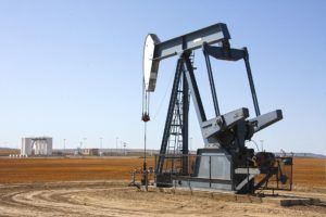
Enhanced Oil Recovery Reservoirs
CO2 enhanced oil recovery (CO2-EOR) can displace oil either by an immiscible or miscible displacement process. Miscibility is where two fluids can be mixed in all proportions, forming a single fluid with no interface between them.
Conversely, immiscible fluids do not form a single phase when mixed.
Immiscible displacement occurs when the reservoir pressure is too low, or the oil composition is too heavy, and the injected CO2 gas does not mix with the reservoir oil.
The minimum miscibility pressure (MMP) finds the minimum pressure required for the reservoir oil to be mixed with carbon dioxide at reservoir temperatures. Miscibility often does not occur in a single point, in many cases multi-contact miscibility is achieved after some gas injection either through condensing gas drive mechanisms or evaporating gas drive processes. Miscible and immiscible displacement processes involve several mechanisms to enhance oil recovery:
- oil swelling
- reduction in oil viscosity
- contribution to solution gas drive production
- and most importantly, significant reduction in residual oil saturation when miscible injection occurs
Recovery occurs when carbon dioxide is dissolved into the crude oil and the volume of the oil increases. As the volume of oil increases, oil is displaced from the pore space leading to enhanced oil recovery. As the carbon dioxide is dissolved into the crude oil, the oil density and viscosity are also reduced, improving the mobility of the oil.
CO2 can also provide a gas drive effect where CO2 supplies added reservoir drive energy. Both in immiscible and miscible displacement processes, the injected CO2 changes the residual oil properties to make it more mobile and extractable.
In some cases, water is initially injected to increase reservoir pressure and to reach MMP before beginning CO2 injection. Some of the best candidate reservoirs for CO2 EOR are mature water-flooded reservoirs with around a 15-25 percent recovery factor. Miscible gas (CO2) flooding in such reservoirs could increase the recovery to 60-90 percent depending on the type of flooding and heterogeneity of the reservoir.
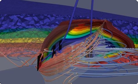
Geology and Geophysics – A Model for CO2 Sequestration
The geologic model of a reservoir allows a better understanding of flow conduits, connectivity to any aquifers, faults and fractures, fluid volumes, reservoir connectivity, and different flow units.
Steps to be completed before the geological model is developed:
- Hydro-geology study to show regional flow patterns. In a regional groundwater flow system, recharge areas are along groundwater divides, and discharge areas lie at the bottom of major drainage basins.
- Perform a mini frack test. A leak-off, step rate, and fracture test analysed to determine fracture pressure for cap-rock and reservoir formations.
- Geo-mechanical study for a targeted reservoir. A review of geo-mechanical response of the reservoir/CO2 storage and surrounding rock to determine the maximum injection pressure and lowest temperature to inject CO2. Evaluation of cap rock is crucial for site selection.
- Evaluate any potential faults and fractures in the caprock overlying the storage formation.
- Review reservoir porosity and permeability based on existing vertical well core analysis and geophysical wireline data.
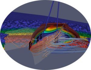
Dynamic reservoir fluid flow simulation for CO2 injection
Proper modelling and analysis of carbon capture and storage will require correct fluid modelling, and exact rock-fluid interaction modelling. In fact, once the geological model is built, the two most vital elements needed for modelling and understanding of CO2 sequestration are pressure-volume-temperature (PVT) and special core analysis (SCAL).
CO2 properties will change significantly with pressure and temperature. Additionally, CO2 miscibility with different fluids can be a complex problem. Many papers are published on experimental data of CO2 interaction with other fluids. If CO2-EOR is the goal, the best approach is to do PVT tests and make a fluid model that matches the experiments.
Otherwise, we can use publicly available experiments with oil properties close to the target reservoir oil and make a fluid model based on that data.
As an example of the complexity of CO2 fluid behaviour. The density of CO2 at the land surface is around 1.9 kg/m3, but the interplay between pressure and geothermal gradients lead to large density increases until ~600–1000 m depth where it reaches densities between 250 and 800 kg/m3.
Capillary pressure and interfacial tension (IFT) becomes important as it dictates residual oil saturation, macro-sweep efficiency of the CO2 flooding, and the amount of CO2 storage.
If CO2 sequestration in aquifers is considered, it is best to follow a compositional approach, as there are only 2 components and run time is manageable while gaining more certainty of the results with a compositional simulator. Compositional simulators have CO2 as one part in the fluid model. In this approach, a normal equation of state (ideally tuned to experimental data) is used to model the interaction of CO2 and other fluids.
Solubility and miscibility could be more accurately modelled using compositional modelling, although it needs good data, and it takes more computing and memory power.
Subsurface workflow in carbon capture and storage
The focus with subsurface workflow is on site characterization. Carbon capture and storage has some workflow similarities with the oil and gas industry, moreover, CO2 storage has some unique geology and geophysics, and reservoir engineering considerations.
The workflows will figure out maximum operating pressure, injection rate, injection pattern, capacity & number of wells, and the economic life cycle of the CO2 sequestration.
The subsurface analysis will include model calibration, economic sensitivity, testing injection scenarios and comparing outputs.
The site characterization is intended to decide if potential sites can be identified as a prospective area, how it is ranked among potential sites in the vicinity, and if it is considered to meet all necessary criteria for regulatory approval.
Special Credits and Contributions by: Miodrag Pancic P.Eng, Moslem Hosseininejad P.Eng, Darrell Cotterill P.Geol.
Planning a carbon capture and storage project?
Vista Projects is an integrated engineering services firm able to assist with your Carbon Capture projects. With offices in Calgary, Alberta, and Houston, Texas, we help clients with customised system integration and engineering consulting across all core disciplines.