Carbon Capture and Storage (CCS) has become top of mind in oil and gas, energy policy, and sustainability conversations worldwide. But few, apart from the geologists and engineers who work directly in CCS, understand what it is.
This article will be the fourth in our series on “What Is CSS” and will serve as an introduction to monitoring, measurement, and verification in Carbon Capture and Storage projects.
CCS is a broad term that represents several technologies which capture carbon dioxide (CO2) emissions from facilities or directly from the atmosphere. The process is designed to help prevent the accumulation of greenhouse gases in the atmosphere to reduce global warming. Once capturing CO2 is carried out it is re-used as a gas in manufacturing processes or is stored via enhanced oil recovery.
There is growing interest in the application of carbon capture and storage technologies to help reduce greenhouse gas emissions in Canada and around the world. This article will provide an introduction into how we monitor, measure, and verify carbon capture processes.

Monitoring carbon capture and storage projects
The purpose of monitoring is to identify possible movement of CO2 that may lead to the release of greenhouse gases into the atmosphere. Such events would require immediate remedial action. Here are the basic steps:
1. Establishing a baseline
Before a project commences, governing bodies require measurement reports to establish a baseline for further operations. This requires a Sequestration Evaluation Permit (SEP) and Carbon Sequestration Lease (CSL).
The SEP must be obtained before acquiring a CSL. The application for an Evaluation Permit must be submitted to the government regulatory body outlining the Measurement, Monitoring and Verification (MMV) plans. The MMV plan includes steps to measure and monitor the atmosphere, soil, groundwater and subsurface to identify potential CO2 leaks.
The Sequestration Evaluation Permit (SEP) grants the right to perform detailed testing and characterization of the surface and subsurface environment.
After information about the carbon capture and sequestration site and reservoir bearing has been gathered and evaluated (for example, approx. 15 years of storage capability), a sequestration lease can be obtained.
2. Carbon capture and storage operations
During CO2 injection the verification process begins. This verification will help confirm the efficacy of the site.
Verification is the comparison of measured and predicted performance of the CCS operations. In CCS it is defined as the set of activities used for assessing the amount of CO2 that is stored underground, and for assessing how much is leaking back into the atmosphere.
3. Post carbon capture operations and discontinuation
Monitoring of carbon capture and storage sites continues for decades, to confirm the surrounding area is unaffected and the CO2 is safely contained in the storage site. Below is just some of the monitoring that is undergone at a storage site.
Types of monitoring and measurement:
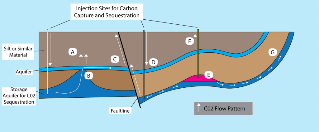
Escape routes and remediations during carbon capture and storage failure:
A)
- Pressure from escaping gas (B) into the aquifer pushes C02 into the silt layer.
- Remediation is to extract and purify groundwater to purge gases and ensure general water table use.
B)
- C02, originally sequestered in a lower storage site, leaks through a connection point between cap rock and upper aquifer.
- To remedy this leak, C02 can be re-collected and injected elsewhere.
C)
- Additional C02 from the aquifer leaks upwards along a fault line.
- Remediation is to extract and purify groundwater to purge gases for general use.
D)
- C02 that was originally injected from the well site, into the storage formation, is pressured upwards via the fault line.
- Remediation requires reconfiguring and adjusting the pressure present at the storage site and monitoring.
E)
- The natural flow of C02 within the storage area slowly drains the sequestering zone of the gaseous C02 pocket.
- A remediation option is to recollect escaping C02 at an intercept location and reinject the C02 gas.
F)
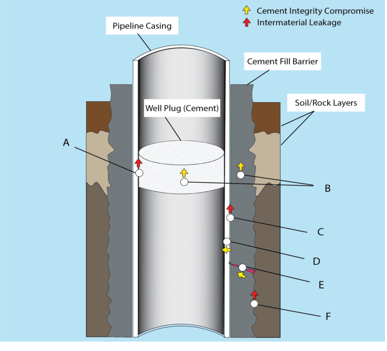
- The abandoned well is unsecured and leaks C02 from underground via methods discussed in Figure 2.
- Remediation requires re-plugging the well with cement and monitoring.
G)
- C02 which has completed the dissolving process follows the aquifer to an escape point such as an open air location, or near surface location which allows it to seep through the ground.
- Again the remediation method is to intercept the leak location and reinject the C02 elsewhere.
Types of Monitoring and Measurement:
Measurement involves surveillance activities required to ensure the safe and reliable operation of a carbon capture and storage project. Monitoring measurements are an important part of the operations and risk strategy for carbon capture and storage projects.
Subsurface instrumentation monitors the movement of the CO2 in the storage site, the stability of the cap rock, and geological formations above cap rock.
Integrity evaluation of new and existing wells (Figure 2)
- Cement bond logs and cement seal testing
- Cement casing integrity logs and corrosion monitoring
- Temperature logs to monitor crossflows and material resistance
- Pressure testing of site to ensure stability
Technologies for monitoring injection rates and pressures/temp
- Monitoring of maximum wellhead injection pressures to ensure that reservoir fracture pressures are not exceeded
- CO2 flow rate system monitoring by combining pressure, temperature, and differential pressure measurements with gas chromatography
- Single mode and multi mode fibre-optic pressure and temperature monitoring systems
Methods of monitoring CO2 reservoir gas migration
- Observation wells equipped with Distributed Temperature Sensing (DTS) and Distributed Acoustic Sensing (DAS) will monitor potential CO2 migration and crossflow above the cap rock.
- Electrical and Electromagnetic surveys in observation wells to understand movement of CO2.
- The use of geochemical monitoring to determine the rate of dissolution of the CO2 into the reservoir fluids. It will also determine the reservoir minerals ability to react with the CO2 and permanently store it.
- The use of tracers (chemical or radioactive) in the injector wells can indicate the path of the CO2 flow by timing the arrival of the tracers at production or monitoring wells.
- Comparison between baseline surveys of water quality and/or isotopic composition can be used to identify CO2 arrival at a specific location from natural pre-existing CO2.
- The chemical changes, increases in acidity, and the bicarbonate ion levels in the fluids.
- Surface sampling for CO2 or tracers in soil and near surface water-bearing horizons.
- Surface CO2 fluxes may be directly measurable by techniques such as infrared spectroscopy.
- Seismic surveys, and cross-well seismic surveys, to understand CO2 distribution in storage reservoirs and formations above the storage formation. The CO2 plume comprises several distinct layers of CO2, each up to about 10 metres thick.
- Passive seismic monitoring to detect micro-seismic events induced in the reservoir by seismic responses to the changes in pore pressures and the reactivation or creation of small fractures.
- Micro-seismic events are extremely small, but monitoring the micro-seismic events may allow the tracking of pressure changes and, possibly, the movement of gas in the reservoir or saline formation.
- Interferometric Synthetic Aperture Radar (InSAR) monitoring with an established baseline would detect heave and subsidence of the surface during the CO2 injection or post injection surface movements.
Environmental Monitoring Systems for Carbon Capture and Storage

Near-surface instrumentation monitors the groundwater to ensure CO2 is not leaking and atmospheric surface instrumentation monitors CO2 levels in the air around the site.
Groundwater
- If CO2 migrates into a groundwater aquifer, potential impacts can be assessed by collecting groundwater samples and analyzing them for major ions, pH, alkalinity, stable isotopes, and gases.
- Natural tracers and introduced tracers may provide insight into the impacts of storage projects on groundwater.
- Introduced tracers such as perfluorocarbons that can be detected at very low levels may also be useful for determining whether CO2 has leaked and is responsible for changes in groundwater quality.
- Synthetic tracers could be added periodically to determine movement in the reservoir or leakage paths.
Air quality and atmospheric fluxes
- Continuous sensors for monitoring CO2 in air are used in a variety of applications, including HVAC (heating, ventilation and air conditioning) systems, greenhouses, combustion emissions measurement, and environments in which CO2 is a significant hazard.
- Common field applications in environmental science include the measurement of CO2 concentrations in soil, air, CO2 ‘flux’ from soils, and ecosystem-scale carbon dynamics.
- Bio-geo-chemists use data from CO2 detectors on 2-5 metre tall towers with wind and temperature data to reconstruct average CO2 flux over large areas.
- Surface monitoring techniques such as visible and infrared imaging from satellites or planes will be detecting and quantifying surface releases; Accurate data baseline will improve the reliability and resolution of all measurements.
Ecosystems
- The condition of terrestrial and subsurface ecosystems can be determined directly by measuring the productivity and biodiversity of flora and fauna.
- In many areas with natural CO2 seeps, reduced plant growth and the presence of precipitants of minerals leached from rocks by acidic water are present.
- Detection of elevated concentrations of CO2 or evidence of excessive soil weathering would indicate the potential for ecosystem impacts.
- For aquatic ecosystems, water quality and in particular low pH, would provide a diagnostic for potential impacts.
The carbon capture and storage in depleted gas reservoirs and enhanced oil recovery (EOR) applications will utilise most of the measurement, monitoring, and verification (MMV) techniques above. However, MMV in EOR application will be slightly different than in depleted gas reservoirs.
Saline aquifers are a frontier for the current CO2 storage technology and MMV techniques will accordingly change to address potential issues and challenges that will arise.
Special thanks to the contributors of this article:
Miodrag Pancic P.Eng, Moslem Hosseininejad P.Eng, Darrell Cotterill P.Geol.
Planning a carbon capture project?
Vista Projects is an integrated engineering services firm able to assist with your Carbon Capture projects. With offices in Calgary, Alberta, and Houston, Texas, we help clients with customized system integration and engineering consulting across all core disciplines.