
A variable frequency drive (VFD) is an electronic motor controller that adjusts an AC motor’s speed by changing the frequency and voltage of the power it receives. With a VFD, the motor can match its output to actual demand, so a pump no longer runs at full speed while a valve wastes the surplus.
Outside the electrical team, VFDs first show up on paper. They appear on the electrical load list and the single-line diagram, then in equipment layouts and energy reports, long before anyone installs one.
The International Energy Agency’s 4E Electric Motor Systems Platform estimates that, in 2023, electric motor systems accounted for 53% of global electricity consumption and 72% of electricity use in industry. In Canada, drives must be certified before installation, and the installation itself must follow the Canadian Electrical Code, CSA C22.1, which Alberta enforces in its 2024 edition.
What Is a Variable Frequency Drive?
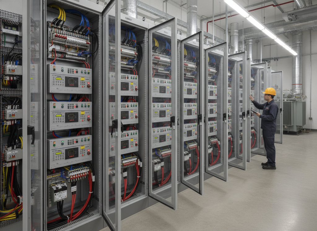
A variable frequency drive is a power electronic motor controller that sits between the electrical supply and an AC induction motor. It converts fixed-frequency utility power to an output with adjustable frequency and voltage. That output sets the motor speed, allowing facilities to match motor output to actual demand.
Connected straight to the grid, an AC motor runs at a nearly constant motor speed set by the 60 Hz supply. Designers size most pumps and fans for peak demand, so the equipment spends much of its life below that peak. Without speed control, operators cut flow with a throttling valve or damper while the motor keeps drawing near full power.
Other Names for a VFD: Variable Speed Drive, Adjustable Speed Drive and More
A VFD is also called a variable speed drive (VSD), adjustable speed drive (ASD), adjustable frequency drive (AFD), AC drive, inverter drive or frequency converter. Variable speed drive and adjustable speed drive are broader terms, so every VFD is a variable speed drive, but not every variable speed drive is a VFD.
How Does a VFD Work?
A variable frequency drive works because an AC motor’s speed follows the frequency of its power supply. Synchronous speed equals 120 × frequency ÷ number of poles, so a four-pole motor turns at about 1,800 rpm at 60 Hz and about 900 rpm at 30 Hz. Actual shaft speed is slightly lower because induction motors slip. To keep the motor’s magnetic field steady, the drive changes voltage in step with frequency. That works out to about 7.67 V/Hz for a 460 V, 60 Hz motor, and about 9.6 V/Hz for the 575 V, 60 Hz motors common on Canadian 600 V systems.
The Three Stages Inside a Drive
Most VFDs use an AC-DC-AC design that handles power in three stages. The rectifier comes first and converts the incoming AC supply to DC, using a six-pulse diode bridge in a conventional low-voltage drive. A bank of capacitors on the DC bus then smooths that voltage and stores energy for the last stage, the inverter. There, fast electronic switches called IGBTs (insulated-gate bipolar transistors) turn on and off thousands of times a second to rebuild AC power at the motor’s required frequency and voltage.
Matrix drives, which are far less common, convert AC to AC directly with no rectifier or DC bus.
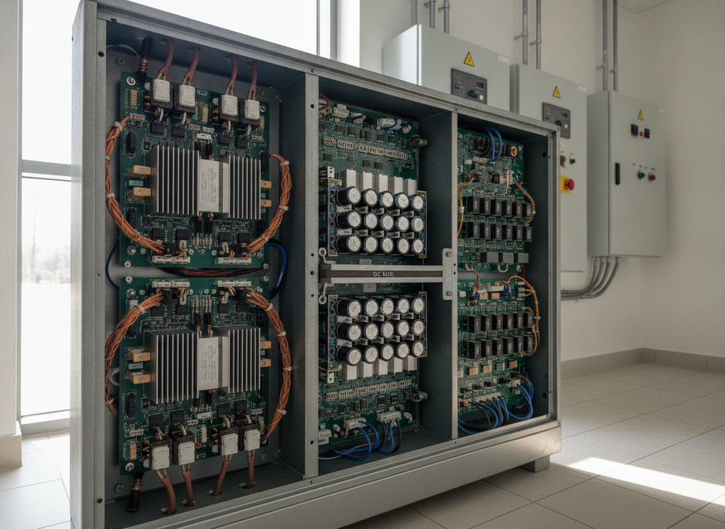
Around those stages sit the controller and keypad, plus the communication ports that tie the drive to the plant. Depending on the model, the drive takes its speed command from a PLC or DCS through a 4–20 mA signal or a network like Modbus or EtherNet/IP, and reports back its speed and current along with any fault codes.
Pulse-Width Modulation in Plain Terms
Instead of a smooth sine wave, the inverter puts out a fast train of full-voltage pulses, a method called pulse-width modulation (PWM). Wider pulses produce a higher average voltage, and narrower pulses produce a lower one. The motor windings smooth the pulses into a current that closely follows a sine wave.
The switching frequency, or carrier frequency, is how fast the switches cycle, usually somewhere between 2 kHz and 20 kHz, and it is separate from the output frequency, which sets motor speed.
Control Methods
Drives differ in how tightly they control motor speed and torque. Volts-per-hertz control is the simplest. It holds the voltage-to-frequency ratio steady and suits pumps and fans well. Sensorless vector control adds stronger low-speed torque without needing a speed sensor, and for precise torque on cranes and hoists, designers turn to closed-loop vector control or direct torque control.
Types of VFDs on Industrial Projects
Most variable frequency drives share that three-stage design, but the type you pick still decides how much space and cooling the drive needs and what it does to power quality.
| Drive type | Common use | What it changes for the project |
| Low-voltage drive | Motors on low-voltage systems, commonly 480 V in the U.S. and 600 V in Canada (575 V motors) | Fits in a motor control centre or a wall-mounted enclosure |
| Medium-voltage drive (2.3 kV and above) | Large motors. Some product lines start around 200 kW, so the cut-over point depends on the project | Footprint and cooling depend on configuration, so compare low- and medium-voltage options where a motor falls in the overlap |
| Six-pulse front end | Standard low-voltage drives | Lowest cost, but the highest harmonic current |
| 12-pulse or 18-pulse front end | Larger drives where harmonics must be limited | Adds a phase-shifting transformer, weight and space |
| Active front end | Drives with strict power quality limits or frequent braking | Near-sinusoidal input current, and it can return braking energy to the supply |
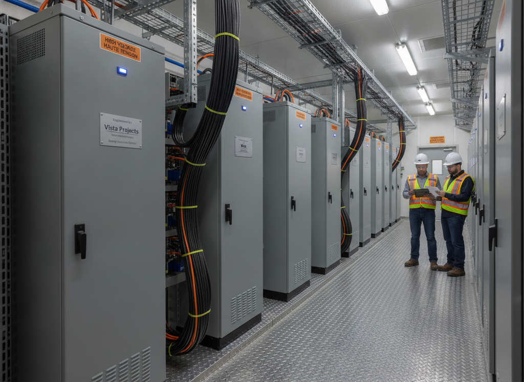
Wall-mounted units serve single motors, and plug-in units sit in a motor control centre, while floor-standing cabinets go in an e-house (a prefabricated electrical building).
VFD Benefits: Why Facilities Use Them
Facilities install variable frequency drives to control motor speed, and most of the benefits follow from that one ability. Matching speed to demand cuts energy use and keeps process setpoints tighter. Gradual ramping gives motors a soft start, and smoother running reduces drivetrain wear. Fans also run more quietly when turned down below full speed.
The biggest draw is energy. Slowing a pump or fan to match demand cuts power far faster than flow, as the next section shows.
Starting a motor across the line draws roughly 5 to 10 times its full-load current, depending on motor design, and subjects the driven equipment to a torque spike. A VFD avoids both by ramping frequency and voltage up gradually, keeping current within the drive’s limit. That protects weak supplies and spares remote sites from oversizing generators just to start motors.
Process control gets tighter too. Paired with a PID control loop in the PLC or DCS, a drive trims motor speed to hold a setpoint, a header pressure or a tank level, for example, without the wear and lag of a control valve.
Gentler starts and stops reduce wear across the drivetrain, from belts and couplings to gearboxes and bearings, and slow pump stops limit the pressure surges known as water hammer.
Fans below full speed also run noticeably quieter, which helps sites with neighbours or noise limits. On the electrical side, the drive improves displacement power factor, although harmonics pull the true power factor back down.
How Much Energy Can a VFD Save?
The energy a variable frequency drive saves depends on two factors: the type of load it runs and how many hours that load spends below full demand.
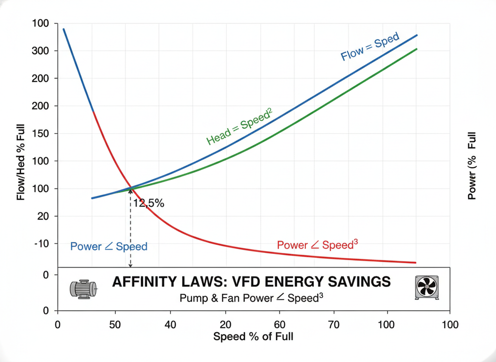
On centrifugal pumps and fans, the affinity laws explain the savings. Flow follows speed directly, and pressure follows its square, but power follows the cube of speed, and that cube is why a small drop in speed delivers large energy savings. The U.S. Department of Energy notes that cutting speed by 20% can cut power by about 50%.
| Motor speed | Power required (ideal system) |
| 100% | 100% |
| 90% | 73% |
| 80% | 51% |
| 70% | 34% |
| 60% | 22% |
| 50% | 12.5% |
Speed Control vs Throttling
Throttling is like holding the accelerator down and using the brake to control speed, while a VFD simply eases off the accelerator.
The U.S. Department of Energy gives a worked example in Motor Systems Tip Sheet #11. An exhaust fan motor draws 16.4 kW at full speed to deliver about 15 kW (20 hp) of shaft power. At half speed, the fan moves 50% of its rated airflow but needs only one-eighth of its full-load shaft power. Using the tip sheet’s part-load efficiencies of 77.8% for the motor and 86% for the drive, the system draws just 2.8 kW, an 82.9% cut in input power.
Variable-Torque vs Constant-Torque Loads
On a variable-torque load like a centrifugal pump or fan, the required torque falls as speed falls, so power drops with the cube of speed. A constant-torque load needs the same torque at any speed, so power falls only in proportion to speed. Drive sizing treats most machines that move material at a steady rate as constant-torque loads, from conveyors and extruders to positive displacement pumps and reciprocating or rotary screw air compressors, as well as cranes and hoists. Check each machine’s actual torque-speed profile, especially on cranes and hoists that lower loads. A VFD still improves control on these machines, but it saves much less energy.
Why Real VFD Energy Savings Are Often Lower
The affinity laws describe an ideal system, where all of a pump’s effort goes to overcoming pipe friction. Many real systems also have static head, a fixed height or pressure the pump must overcome regardless of flow. A pump like that cannot slow down far before flow stops, so the affinity laws overstate the energy savings. A centrifugal pump filling an elevated tank saves far less than one circulating water around a closed loop.
Drive efficiency also drops at light load. In the same U.S. Department of Energy tip sheet, a representative 75 kW (100 hp) drive is about 97% efficient at full load and about 89% at 12.5% load. Estimate savings from the real load profile and duty cycle, not the cube law alone. For payback and total cost of ownershipThe total cost of ownership refers to the total cost of owning an industrial asset throughout its full lifecycle, from design and constructi..., see Vista’s guide to selecting energy-efficient equipment for industrial facilities.
Where VFDs Are Used: Pumps and Fans, Compressors and More
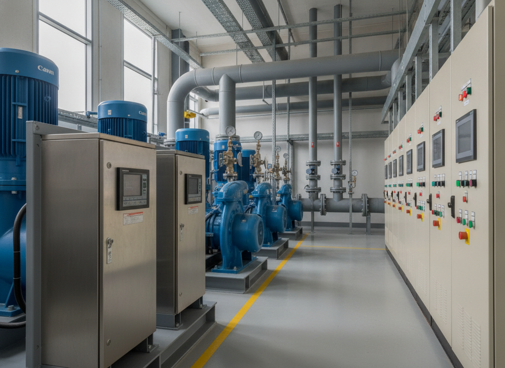
Variable frequency drives are most common where pumps and fans run long hours at changing demand.
In industrial water and effluent treatment, drives sit on the feedwater and effluent pumps and on aeration blowers, where demand rises and falls with production. Industrial HVAC uses them on ventilation fans for e-houses and process buildings and on cooling tower fans.
Process plants and Alberta’s oil sands drive process and produced-water pumps and compressors. Air-cooled heat exchanger fans are another common fit, and heavy oil sites, including steam-assisted gravity drainage (SAGD) facilities, add the electric submersible pumps that lift fluid from wells. In mining and mineral processing, drives run conveyors and slurry pumps.
VFD Disadvantages: Limitations and Trade-Offs
Variable frequency drives bring real but manageable trade-offs, covered below, from harmonics on the supply side to bearing currents at the motor and heat in the electrical room. Each one needs a decision during design, not a fix after start-up.
VFD Harmonics and Power Quality
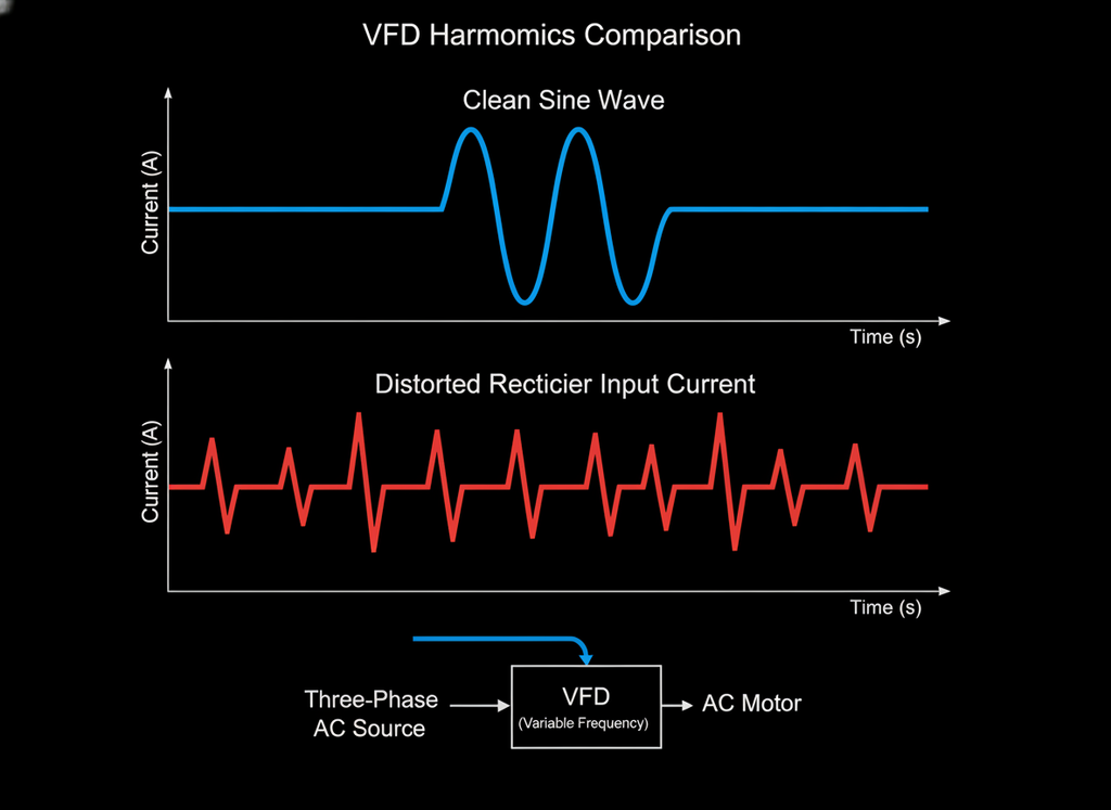
A VFD’s rectifier draws current in short pulses instead of a smooth sine wave, creating harmonic distortion in the facility’s electrical supply. Left unchecked, harmonics overheat transformers and cables, and sensitive electronics on the same supply start to misbehave. Capacitor banks also need a close look, since they can resonate at harmonic frequencies.
Limits apply at the point of common coupling, where the facility connects to the utility system. IEEE 519-2022, from the U.S.-based IEEE, sets voltage distortion limits of 8% at 1 kV and below, and 5% above 1 kV up to 69 kV. Canadian utilities set their own rules, and several reference an edition of IEEE 519. Check your utility’s current requirement, because it takes precedence.
Solutions range from simple line reactors or DC chokes to multi-pulse drives fed by phase-shifting transformers, active front ends, and harmonic filters, and a harmonic study of the whole electrical system shows which combination a site needs.
Voltage Spikes on Long Motor Cables and Inverter-Duty Motors
Fast voltage pulses from a VFD’s inverter reflect at the motor terminals, and on longer cables the reflections stack up and push the peak voltage well above normal. Drive manufacturers publish a maximum motor cable length for each model, so check it early. Inverter-duty motors built to NEMA MG 1 Part 31 are designed for the faster, higher voltage peaks a drive produces, while general-purpose motors are not. In Canada, the motor also needs CSA C22.2 No. 100 certification.
The simplest fix is to keep the drive close to the motor, and where the layout does not allow it, dV/dt (voltage-rise) or sine-wave filters and an inverter-duty motor protect the windings.
Bearing Currents
PWM drives also put stray voltage on the motor shaft. When that voltage discharges through the bearings, it pits the races in a washboard pattern called fluting, and the bearings fail early. To prevent it, U.S. Department of Energy guidance calls for a shaft-grounding brush and insulated bearings on inverter-duty motors above the NEMA 500 frame size, and a lower carrier frequency where bearing damage is a risk.
Motor Heating at Low Speed
Most industrial motors cool themselves with a fan on their own shaft, so cooling drops as they slow down. That is rarely a problem on a variable-torque load, which falls off quickly with speed. A constant-torque load at low speed can overheat a standard motor, though. An inverter-duty motor handles a wider constant-torque speed range, and larger frames can add a separately powered cooling blower.
Heat, Space and Cost
A few percent of the power passing through a drive turns to heat, about 3% for the U.S. Department of Energy’s representative 75 kW drive at full load, and a larger share at light load. In an electrical room or e-house full of drives, that heat becomes a serious cooling load for the HVAC design. The drives themselves, along with their reactors and filters, also take up floor and wall space and add capital cost.
[CTA: Planning VFDs for an Industrial Project? Talk to Our Experts]
Installation and Site Safety for VFDs
Most variable frequency drive trade-offs are settled in design, but a few are decided or enforced on site.
Environment and Enclosures
Check the ambient temperature range on the drive’s current certification listing. In Alberta winters, outdoor drives or those in unheated buildings need heated, ventilated enclosures or a climate-controlled e-house. Drives normally sit in an unclassified electrical room, but motors out in hazardous areas must be certified for drive-fed operation, and Section 18 of the Canadian Electrical Code sets the rules for hazardous locations (see hazardous area classification).
Cabling and Grounding
Route drive output cables away from instrument cables to keep electrical noise off nearby control signals (see cable trays). Provide a low-impedance bonding path from the motor frame back to the drive, as drive manufacturers recommend. Confirm the bonding method against Section 10 of the Canadian Electrical Code with your authority having jurisdiction.
Stored Energy After Shutdown
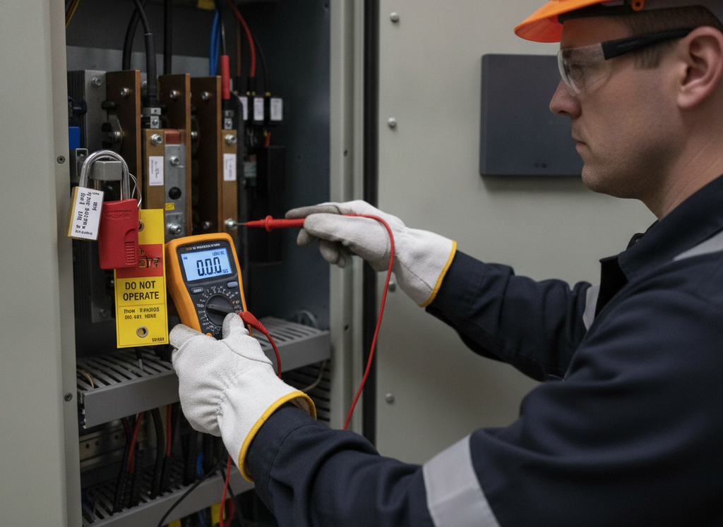
Switching a VFD off does not make it safe, because its DC bus capacitors can hold a lethal charge. Before opening a drive, isolate the supply under the site’s lockout/tagout procedure, written to CSA Z460 and Part 15 of the Alberta OHS Code or your province’s equivalent. Then wait out the discharge time listed on the drive’s warning label, which varies by drive. After that, verify zero voltage across the DC bus with a properly rated meter. A dark display or unlit charge light does not prove the drive is safe. Energized work on a drive, like testing or troubleshooting with the covers off, also requires a shock and arc flash risk assessment under CSA Z462.
Commissioning Checks
- Enter the motor nameplate data, then run the drive’s auto-tune routine.
- Set acceleration and deceleration ramps to suit the process and piping.
- Set a minimum speed that keeps pumps above their minimum flow.
- Program skip frequencies to avoid speeds that excite mechanical resonance.
- Confirm motor rotation before coupling the driven equipment.
Spares and Service Life
Manufacturers publish replacement intervals for cooling fans and DC bus capacitors, and heat and dust shorten both. For spare drives stored without power for an extended period, follow the manufacturer’s guidance on capacitor reforming.
What a VFD Decision Means for Your Project
On a drawing, a variable frequency drive looks like a single line item. In practice, putting a drive on a pump or fan changes the work of most disciplines on an industrial project.
| Discipline | What a VFD decision changes |
| Process | Turndown range, duty points and control philosophy |
| Mechanical | Pump and fan selection across the speed range, minimum speed limits |
| Electrical | Drive rating and type, harmonic study, cable lengths, electrical load list, single-line diagram |
| Instrumentation and controls | Speed signals, interlocks, safe torque off, networks, cybersecurity (IEC 62443) |
| Civil and structural | E-house foundations, cable trench and tray routes, building footprint |
| HVAC | Heat load from drives, reactors and filters |
| Environmental compliance | Energy baseline, emissions reporting, utility harmonic limits, noise |
| Operations and maintenance | Spares, fan and capacitor replacement, operator training |
Settle which motors get drives during front-end engineering design, while changes are still inexpensive. Adding a drive late in detailed design rarely stops at the drive. The electrical room has to grow to fit it and its filters, which move the cable routes and the foundations under them, and most of that ends up as rework in the field. Strong interdisciplinary coordination stops one change from spreading unnoticed.
Vista Projects set up an Owner-Controlled Digital Execution Environment for a major oil and gas owner-operator’s downstream facility expansion. The owner controlled the project data, and every engineering contractor worked inside the owner’s hub, so every discipline worked from the same current information. During FEED, the team cut the time needed to produce a material take-off-based cost estimate by two-thirds.
Standards and Codes That Apply in Canada
In Canada, CSA standards and provincial regulations take precedence and govern every stage, from how a VFD is built to how it is installed and connected to the grid. The U.S. and international standards in the table apply only where a Canadian code, utility or project specification adopts them.
| Standard | What it covers |
| CSA C22.2 No. 61800-5-1 | Safety standard for adjustable speed drive systems |
| CSA C22.1 (Canadian Electrical Code), Part I | Installation of drives, motors and their wiring |
| CSA C22.2 No. 100 | Safety of motors and generators |
| CSA Z462 | Workplace electrical safety and arc flash risk assessment |
| CSA Z460 | Control of hazardous energy, including lockout |
| Alberta OHS Code, Part 15 | Hazardous energy control on Alberta worksites |
| IEEE 519-2022 | From the U.S.-based IEEE, for international use. Harmonic limits at the utility connection, where adopted |
| NEMA MG 1 Part 31 | U.S. standard for inverter-duty motors |
| IEC 61800 series | International drive system standards, including functional safety in IEC 61800-5-2 |
In Alberta, Vista Projects delivers engineering services under APEGA oversight. Engineering work in other provinces falls under each province’s own regulator.
Frequently Asked Questions About VFDs
What is the difference between a VFD and a VSD?
A VFD is a type of variable speed drive (VSD) that controls an AC motor by changing the frequency and voltage of its supply. The broader VSD category also covers DC drives and mechanical methods like hydraulic couplings.
Can a VFD be used with any AC motor?
Many three-phase AC induction motors can run on a VFD, but PWM drives can damage unsuitable motors. Check rated voltage, cable length, insulation, cooling, bearings and speed range first. Specifying an inverter-duty motor guards against voltage spikes on long cable runs and overheating on constant-torque loads at low speed. Single-phase motors are a poor fit because VFDs are built to run three-phase motors.
Is a VFD the same as a soft starter?
No. A soft starter only reduces voltage during startup, then lets the motor run at full speed. A VFD provides the same gentle soft start, then continues to control speed while the motor runs. Soft starters cost less, especially at larger horsepower, and with a bypass contactor, they add virtually no harmonics at full speed. They suit equipment that never needs to slow down, while a VFD suits changing demand.
Can a VFD run a motor faster than its rated speed?
Yes, within limits, because a VFD can push output frequency above 60 Hz. Past the motor’s nameplate speed, available torque falls, so the motor still cannot deliver more than its rated power. The limit depends on motor design, so check the manufacturer’s maximum safe speed, and confirm that the driven equipment and couplings are rated for the higher speed.
Does a VFD save energy on every motor?
No. A VFD saves the most energy on variable-torque loads, like centrifugal pumps and fans that spend long hours below full demand. Savings shrink on constant-torque loads and on pumps working against high static head. On a motor that always runs at full speed, the drive’s own losses, about 3% at full load for the U.S. Department of Energy’s representative 75 kW drive, can mean slightly higher energy use than a direct-on-line starter.
How long does a VFD last?
A well-maintained VFD outlasts its cooling fans and DC bus capacitors, which wear out first. Manufacturers publish replacement intervals for both, and heat and dust shorten them, so a clean, cool electrical room extends drive life.
Can a VFD convert single-phase power to three-phase?
Some small VFDs can, which lets a three-phase motor run where only single-phase power is available. If the drive is rated for three-phase input, expect to derate (oversize) it, because its rectifier and DC bus carry more stress on a single-phase supply. Some drives are rated for single-phase input without derating.
What is regenerative braking in a VFD?
On a lowering crane hoist or a downhill conveyor, the load drives the motor faster than its set speed. The motor then acts as a generator and pushes energy back to the drive. A standard, non-regenerative VFD cannot pass that energy back to the line, so its DC bus voltage rises. Fitted with a braking chopper and resistor, it dissipates the energy as heat. Without one, the drive trips on overvoltage unless the design gives the energy somewhere else to go. A longer deceleration time is the simplest fix, and drives on a shared DC bus can pass the energy to a neighbouring drive that’s powering its own motor. A regenerative drive, like one with an active front end, returns the energy to the supply instead, which pays off where braking is frequent.
Plan Your Drives While the Design Is Still Flexible
Whether a drive pays off depends on what it runs. A centrifugal pump that spends long hours below full output saves far more than one pushing against high static head. The trade-offs work the same way, since harmonics and heat are cheap to plan for and expensive to fix once the drive is in. Handled early, a drive’s trade-offs stay design decisions, not field fixes.
If VFDs are part of an upcoming facility or retrofit, talk to Vista’s engineering team about planning them early.
Planning Drives for a New Facility or Retrofit?
Talk to Vista’s Engineering Team
This article reflects Canadian standards and Alberta regulations, and licensing and code requirements differ in other provinces and jurisdictions. Confirm them with the authority having jurisdiction before you apply them to a project.