Carbon Capture and Storage (CCS) has become a hot-button topic in oil and gas, energy policy, and sustainability conversations worldwide. But few, apart from the geologists and engineers who work directly in CCS, understand what it is.
This article is an introduction to the process and science of CCS, so that it can be understood by everyone.
What is carbon capture?
CCS is the only viable technology to mitigate carbon emissions while allowing continued large-scale use of fossil fuels. To carry out CCS is to prevent carbon dioxide (CO₂) from being released into the atmosphere from biological or industrial processes.
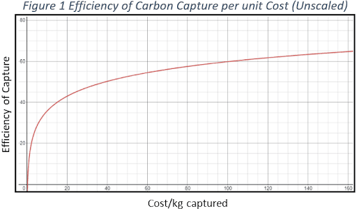
The idea is to intercept pollutants between the point at which they are emitted and the point they are absorbed into the atmosphere. CCS is used by heavy industries to reduce their greenhouse gas emissions. Currently, these processes yield a capture rate of +90 per cent when done correctly. However, the affordability of CO₂ capture falls drastically as efficiency approaches 100 per cent (see chart).
Carbon Sequestration
Carbon sequestration is the act of absorbing and storing carbon dioxide over a lengthy period to prevent it from entering the atmosphere. Sequestration of carbon might be biological or geological.
In non-organic examples it is stored in deep geological formations or in the form of mineral carbonates. This provides for the stability of carbon in both solid and dissolved forms, preventing an increase in atmospheric temperature. CCS is the process of capturing emitted carbon dioxide, transporting it for storage, and depositing it in a way that prevents it from entering the atmosphere. Carbon sequestration occurs naturally over many years once the storage is complete.
Forms of carbon capture in oil and gas
The technologies most widely applied for carbon capture and storage are used at the source of the emissions. They fall into the following categories of capture:
Post Combustion
This is the primary method of carbon capture used in power plants. Capture occurs once flue gas is generated following the combustion of a carbon-based fuel such as natural gas or coal. Once the energy from combustion is created, pollutants will be diverted to a separate chamber for CO₂ collection. The remaining treated flue gas is often burned, while the captured CO₂ is compressed and prepared for storage.
These carbon-based energy sources make up ~66 per cent of energy generation capacity in North America. This means that post combustion carbon capture is critical if CO₂ emission reductions are to become a reality.
The greatest challenge of successful and efficient post combustion capture is separating the carbon from the flue gas. Each type of fuel combustion contains different elements and amounts of CO₂. Capture methods must be purpose built for each type of energy source.
Pre-Combustion
Popular in industrial processes, the CO₂ is removed from fossil fuels before the combustion of these fuels is completed. For example, coal is heated under pressure to create a synthesis gas – a process known as gasification. This gas contains hydrogen, carbon monoxide, CO₂, and several other lesser components.
This ‘syngas’ is then combined with water to convert the carbon monoxide (CO) in the syngas into CO₂. The CO₂ is separated from the mixture and captured along with the original CO₂ present in the syngas. The now hydrogen rich mixture is then burned for energy without releasing CO₂.
Because of the higher levels of hydrocarbons present before combustion, pre-combustion capture is often more efficient, but more expensive due to the additional processes required for capture. It is not cost effective to retrofit old facilities with this technology at this time, so its capabilities are not as well-tested.
Oxy-Fuel combustion
A relatively new approach to power generation, oxy-fuel combustion uses a near pure oxygen gas (O₂) to burn coal or natural gas. The carbon fuels chemically react with the oxygen resulting in a steam containing water and CO₂.
The result is a more concentrated stream of CO₂ which is much easier to capture. The captured CO₂ can then be repurposed as coolant, sold for use in manufacturing processes, or stored for sequestration. The result is a capture rate of 90 per cent or greater with very few material inputs.
Potential CO2 sequestration candidates
Once the carbons are captured, they must be transported and stored. For underground storage, a footprint for the CO₂ sequestration area will be identified by an entity with mineral rights, or entities who would like to acquire mineral rights for CO₂ injection.
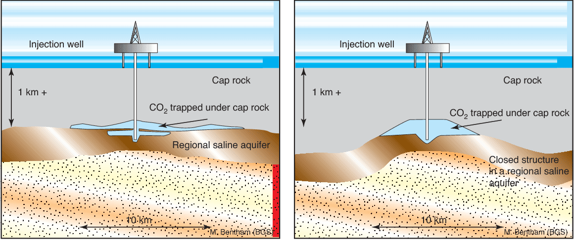
Saline aquifers
Aquifers are made of a porous and permeable rock which is saturated with water. The top layers are commonly used for drinking. However, deeper underground the aquifer salt content makes it non-potable. Of all the potential reservoirs that are considered for carbon storage, deep saline aquifers provide the greatest potential storage capacity.
As seen in the diagram, a layer of impermeable rock traps the carbon dioxide inside the aquifer, where it then dissolves into the saline water. The CO₂ is injected into the aquifer by a prepared pipeline which has breached the rock layer. These hydrocarbons are in a supercritical state (both gaseous and liquid) which is lighter than water. When injected, the supercritical CO₂ floats up to the impermeable rock layer. It then slowly dissolves into the saline water and is sequestered within the aquifer.
Deep saline aquifers are one of the largest identified CO₂ storages in Alberta. Multiple aquifers are identified as potential storages: Wabamun, Nisku, Leduc, Cooking Lake, Swan Hills Member (Beaverhill Lake Group), and Basal Cambrian Sandstone. Injection/storage of CO₂ into deep saline aquifers is a multiphase flow system, where geomechanics, geochemistry, thickness, petrophysical characteristics, and continuation of the formation are important.
Depleted gas reservoirs
A depleted gas reservoir will not be an empty space. The pore space, which was once occupied by oil and gas, will be replaced by injected saline formation water. The advantage is that the reservoir becomes under-pressured as the hydrocarbons are extracted. CO₂ along with other fluids should be easier to inject and the reservoir capacity should be greater with the hydrocarbons removed.
Once the oil or gas is extracted, and saline water injected, the well is then pumped with CO₂ until the predetermined pressure is reached. The amount pumped into a given reservoir varies greatly due to differences in size, geological composition, and stability.
Once the storage is complete, the well is ‘capped’ and undergoes long term monitoring to ensure the integrity of the reservoir. Depleted gas reservoirs are the best candidate for carbon dioxide storage. Primary gas production followed by injection of carbon dioxide as a secondary gas recovery has long been one of the industry practices. CO₂ injection depends on the current reservoir depletion, reservoir characteristics, operational parameters, and injection strategy.
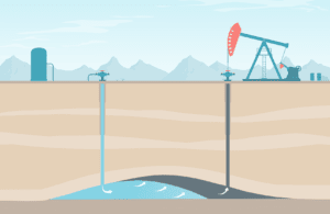
Enhanced oil recovery reservoirs
Enhanced oil recovery or (EOR) is the process of injecting CO₂ into an existing oil reservoir. By injecting carbon dioxide into the well, overall pressure in the reservoir increases, pushing the oil towards the production wells. The carbon dioxide also makes the oil less viscous. Allowing for easier movement and collection.
As the CO₂ is pumped underground it is sequestered as the oil is recovered. Allowing for both greater oil extraction efficiency and carbon capture. Selling CO₂ for EOR can provide revenue to CCS facilities, incentivizing further implementation of CCS technologies.
Vista has engineered facilities that are on the cutting edge of enhanced oil recovery (EOR) technology. Achievements working on a variety of EOR projects include:
- Reduced piping quality and cost through plot plan optimization
- Eliminated the need for water treatment unit using EDTA (Versene) as a softening option
- Reduced pumping HP requirements by introducing alkaline and surfactant chemicals upstream of the polymer injection pumps
- Reduced the necessary temperature for heated water heating, saving operational production expenses
- Implemented alternate caustic solutions (sodium hydroxide vs. soda ash)
We offer clients our expert knowledge of EOR techniques:
- Alkaline surfactant polymer (ASP)
- CO2
- Diluent recovery
- Miscible, polymer, and water flooding
- Polymer blending
Carbon capture utilisation and storage process
To better understand the industrial inputs and timeline of carbon capture projects, here is a general outline of a Carbon Capture Utilisation and Storage Process (CCUS) from start to finish.
A typical CCUS process involves the following steps:
- G&G – modelling
- Dynamic simulation for CO2 injection
- CO2 capturing facility and processing capacity
- CO2 pipeline capacity
- Pad compression facility and metering
- CO2 injection operations and life cycle assessment
- Economic modelling
- Surface land and mineral rights acquisition
- Regulatory Applications for CCUS
- Well integrity evaluation in existing reservoirs
- New reservoir/storage development
- Subsurface reservoirs monitoring and shallow formations monitoring
- Surface heave/earth movement monitoring
- Site and well abandonment strategy