In this post, we’ll go over the basics of how to read engineering drawing symbols.
How to Read an Engineering Drawing Symbol
Engineering drawings are simple to pick up and use – once you understand how to read them. Unlike a model, engineering drawings offer more specific detail and requirements, such as:
- Dimensions
- Tolerances
- Finish
- Geometry
- Hardware
- Material type
- Finish
Often models are used in conjunction with engineering drawings to show a good visual representation.
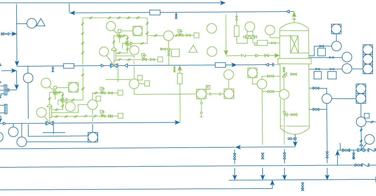
P&ID Engineering Drawings
P&ID engineering drawings differ from the typical mechanical variant; they include:
- Mechanical equipment
- Control instrumentation and designation
- Computer-controlled systems
- Standardized components
- Process piping sizes and identification
Specific piping data can be read from a diagram, including:
- Pipe classes and piping line numbers
- Flow direction
- Interconnection references
- Permanent start-up, finish and bypass lines
- Pipelines and flow lines
- Blinds and spectacle blinds
- Insulation and heat tracing
To find out how to draw P&ID, click here, and to understand how to mark up a drawing in real-time, click here.
PFDs of a Single Unit Process
PFDs differ from P&IDs, showing a more general overview of a system. PFDs of a single unit process include:
- Process piping
- Major equipment items
- Major bypass
- Operational data
- Process stream name
They are far less detailed and shows the system overall.
Engineering Drawing Abbreviations and Symbols
To read an ED, you must first become familiar with the various symbols, abbreviations, and diagram basics.
Once you familiarise yourself with these features, you’ll be able to trace the lines in a system to understand specific components and the overall function in the case of PFDs and P&IDs or understand the manufacture and assembly of a product in the context of mechanical engineering.
PFD Equipment Symbols
PFDs use specific shapes to represent different equipment, valves, instruments, and piping flow in a system. They are a standard set of symbols used for the identification of measurements and functionality within the process.
To provide detail about the components, a 5 letter system is used:
- (Letter 1) L1 – Measured value
- L2 – Modifier
- L3 Readout/passive function
- L4 Output/active function
- L5 Modifier
This is followed by a loop number unique to the loop.
This is also known as a “Tag” identifier of a field device, which is normally given to the measurement’s location and function and identifies it’s on the same loop.
To find out more about specific standard PFD symbols, click here, and for P&ID symbols, click here.
Components of an Engineering Drawing
Several features describe a component, such as lines, views, and title-blocks.
Types of Line
Lines in an ED show both visible and hidden edges of a part, centerlines, etc. – meaning not every line is equal.
Continuous Line
A continuous line (also referred to as a drawing line) represents an object’s physical boundary. In simple terms, these lines draw out the object.
The line thickness can vary, with the outer contours represented by thicker lines and the inner contours by thinner lines.
Dashed Lines
Dashed lines (also referred to as hidden lines) show something that would otherwise not be seen on the drawing. These are seen in instances such as showing an internal step in a turned part without the need for a section or cut-out view.
Dash-Dot lines
Dash-dot lines are used as center lines to indicate the center lines of a hole or show a part’s symmetric properties. This can help reduce the number of dimensions and annotations on a drawing to prevent over detailing.
Extension Lines
Extension lines (two vertical lines joined by a double-headed arrow) annotate what is being measured. The measurement can sit on top or inside the lines.
Break Lines
Break lines (continual lines with intermittent zig-zags) indicate that a view has been broken. They condense the data into a smaller amount of space, for example, in a symmetric or continuous uniform component.
Cut-out Lines
Cut-out lines (two arrows joined by a dash-dot line) are used to show the cutting plane and trajectory of the cut out in a cut-out view.
Views
There are several common views in mechanical engineering and manufacturing drawings. Each view should serve a purpose and be used to communicate vital details.
As with dimensioning, as few as possible views should be used; only necessary items should be shown. A view should only be included if it contributes to the overall understanding of the design.
Isometric View
An isometric view shows a 3-D view of the part. In this type of view, vertical lines – as seen on 2-D drawings – remain vertical, and parallel lines are shown at a 30-degree angle to the horizontal.
Vertical and parallel lines remain true in length, making dimensions transferable when scaling a drawing. Angled lines do not indicate dimensions.
An isometric view can often be confused with a perspective view. However, a perspective view represents an object as it seems to the eye; isometric views stay true to the dimensions instead of creating an optical illusion.
Orthographic View
Orthographic views are crucial to EDs – they are fundamental in detailing the mechanical and geometric properties of a component. An orthographic view or projection represents a 3D object in 2 dimensions. This 2D view conveys any necessary detail for a part to be produced. This avoids any distortion of lengths, as seen on other views.
To communicate all necessary data, three common views are used in multi-view drawings:
- Front view
- Top view
- Side view
Additional views may be required.
Two types of projection styles dictate the layout and interpretation. These are first-angle and third-angle projection; they decide the positioning of the views. First-angle projection is typical in Europe, third-angle projection is usually seen in America and Canada.
Flat Pattern View
A flat pattern view is used to represent a bending pattern for a folded sheet metal part. It represents the geometry when bent after being cut from the sheet metal.
Section View
A section view is used to display part features that are not evident in standard views. Cross-section views are preferred over hidden lines (as mentioned earlier), as they bring more clarity.
Cross hatching is used to represent solid material for cross-section views.
Cut-out View
A cut-out view features cross-sectional views on a normal orthographic view, for example, to show a tapped segment without the need for a full section view. It is used to reduce the number of views required on a specific drawing.
Detailed View
A detailed view gives a close-up of a selected section to show in more detail. They are useful to show dimensioning in a small area, which is part of a much larger sketch.
Auxiliary View
An auxiliary view is an orthographic view that represents planes that are not horizontal or vertical. It shows inclined surfaces without distortion.
Dimensions
An ED shows all necessary dimensions for producing a part. Not every measurement of every line is required – this is over dimensioning and means the manufacturer cannot guarantee that all dimensions are 100% correct.
Crucial details for dimensions are geometric dimensions and tolerances (GD&T). The limits and fits are important in guaranteeing a longer life with less maintenance.
Lower and upper limits or fit classes are essential in a mechanical or manufacturing drawing.
Information Blocks
Another key aspect of an ED is information blocks; they contain necessary detail about the part’s assembly. They are often in the bottom right-hand corner of the drawing/part. They provide detail about what the drawing is for, who it’s for, the part number and short description, and detail on the material and finish.
Title-Block
The title-block serves as the background in which the drawing should be interpreted. It contains:
- The name and address of the company who produced/ owns the drawings
- The part number and description
- Mass
- Material
- General tolerances
- Units
- Finish
- Projection details
- Scale
- Revision number
- Status of the drawing
In some cases, specific data detailed on the drawing may conflict with the more generic title block; in this case, the notes outside of the title-block should be considered correct.
Assembly Drawings
To avoid all the various minute detail of individual parts on an assembly drawing (which can make them complicated to read) – assembly drawings can be used in conjunction with part drawings.
An assembly drawing should clearly detail where each part goes and how it is attached. Exploded views, section views, cut-outs, detailed views, numbered parts, and general dimensions are used to detail the assembly of a product or system.
FAQ
- Dimension text
- Dimension lines and arrows
- Extension Lines
- Gaps
These are uniform across the drawing to prevent confusion. Units for the dimensions are found in the title block.
- When scaling down, i.e., 1:10, the drawing is ten times smaller than in real life.
- When scaling up, i.e., 10:1, the drawing is ten times bigger than in real life.